Free 186 More Best Homemade Tools eBook:  
Get 2,500+ tool plans, full site access, and more.

User Tag List

Results 1 to 10 of 10

Thread: YADH - Yet Another Dividing Head

  1. #1
    Supporting Member EclecticNeophyte's Avatar
    Join Date
    Apr 2013
    Location
    TriCities, WA.
    Posts
    82
    Thanks
    42
    Thanked 118 Times in 35 Posts

    EclecticNeophyte's Tools

    YADH - Yet Another Dividing Head

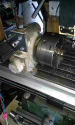
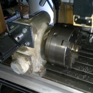
    YADH - Yet Another Dividing Head-20151008_123210.jpg YADH - Yet Another Dividing Head-20150905_153335_resized.jpg

    Pictured above, is a dividing head I built from a gear reduction drive that I found at the local metal recycle yard. There were a number of them laying in a pile, and I grabbed a pair that looked to be suitable for my purposes. As it turned out, the gear box had a 60 tooth worm gear and worm. The input and output shafts were fitted with tapered roller bearings by the manufacturer, which meant they could handle any loads I would be presenting it with. The gear drives were cheaply aquired, as the recycle yard sells items like these, at scrap mixed-metal prices (by weight). As soon as I arrived home, I set about refurbishing them. After a good cleaning, machining, installation of new bearings, etc, one of them was ready for service. I coupled the input shaft to a 400 step stepper motor, and an Arduino controller with motor driver and power supply (also described on this site).

    Also mentioned in an earlier tool post of mine, I recently purchase a used 10" South Bend lathe. This allowed for production of a threaded adapter, giving me the ability to fit a 3 or 4 jaw lathe chuck (or backing plate) to the output shaft of the gear drive. The gear drive output shaft was originally designed to drive from either end. Not wanting the interference of a shaft end opposite of the one I planned to use, the undesired end was cut flush with the outside of the gear drive housing. I used the off-cut from the output shaft, to make a input shaft coupler for the stepper motor.

    In total, the 60:1 worm drive coupled with the 400 step stepper motor, gives a resolution of 24,000 divisions. While I don't plan to cut 24,000 tooth gears, I think it does provide for a greater range of divisions.

    Thanks for reading, and I hope you find this useful!

    -EN

    186 More Best Homemade Tools eBook

  2. The Following 5 Users Say Thank You to EclecticNeophyte For This Useful Post:

    Jon (Mar 18, 2016), kbalch (Mar 23, 2016), Paul Jones (Mar 23, 2016), PJs (Mar 22, 2016), Workshopshed (Mar 22, 2016)

  3. #2
    Supporting Member scrdmgl's Avatar
    Join Date
    Oct 2013
    Location
    Toronto, Ontario, Canada
    Posts
    26
    Thanks
    5
    Thanked 44 Times in 15 Posts

    scrdmgl's Tools
    Hi Neophyte:

    I read your article about your Dividing Head adaptation and it so happens that I'm planning a similar conversion using a 10" Rotary Table. To that effect, I decided (empirically) to go for a NEMA 23 Stepper Motor 200 steps, 24 V, 3A, 360 oz.in double shaft to allow attachment of a crank wheel at the other end. Since I don't have the capacity to program o assemble a driver and controller, I decided to go for a "stand alone" Programmable Driver/Controller sold by a guy by the name of Bryan Mumford in California.
    It looks like a big calculator and can do all kinds of stuff including jogging and continual rotation plus makes built-in adjustments for "slack" or free play. By the way you obviously run into that situation, were you able to program your controller accordingly?
    Also, what size and specs is your motor? If you wish you can write to me at scrdmgl@gmail.com

    Regards from Toronto, Canada

    Jorge
    2,500+ Tool Plans

  4. The Following User Says Thank You to scrdmgl For This Useful Post:

    Paul Jones (Mar 23, 2016)

  5. #3
    kbalch's Avatar
    Join Date
    Jun 2012
    Location
    Clermont, FL
    Posts
    5,034
    Thanks
    2,275
    Thanked 532 Times in 384 Posts
    Hi Jorge,

    Welcome!

    Sounds like an interesting and ambitious project! Please do keep us posted on your progress. Do you have any pics of the rotary table conversion underway?

    Ken

  6. #4
    Supporting Member scrdmgl's Avatar
    Join Date
    Oct 2013
    Location
    Toronto, Ontario, Canada
    Posts
    26
    Thanks
    5
    Thanked 44 Times in 15 Posts

    scrdmgl's Tools
    Hi Ken:

    Not yet since is a work in progress. What about my power source specs. and yours? Were you able to program a 0 slack feature in your code? You can look for my first thread under Metal & Wood Trimmer; I just posted it a while ago.

    Cheers

    Jorge

  7. #5
    Content Editor
    Supporting Member
    DIYer's Avatar
    Join Date
    Aug 2013
    Posts
    3,055
    Thanks
    796
    Thanked 1,895 Times in 1,690 Posts
    Thanks EclecticNeophyte! We've added your Dividing Head to our Machining category, as well as to your builder page: EclecticNeophyte's Homemade Tools. Your receipt:

    Last edited by Jon; Oct 23, 2021 at 01:53 AM.

  8. #6
    Supporting Member EclecticNeophyte's Avatar
    Join Date
    Apr 2013
    Location
    TriCities, WA.
    Posts
    82
    Thanks
    42
    Thanked 118 Times in 35 Posts

    EclecticNeophyte's Tools

    Unhappy

    Quote Originally Posted by scrdmgl View Post
    Hi Neophyte:

    I read your article about your Dividing Head adaptation and it so happens that I'm planning a similar conversion using a 10" Rotary Table. To that effect, I decided (empirically) to go for a NEMA 23 Stepper Motor 200 steps, 24 V, 3A, 360 oz.in double shaft to allow attachment of a crank wheel at the other end. Since I don't have the capacity to program o assemble a driver and controller, I decided to go for a "stand alone" Programmable Driver/Controller sold by a guy by the name of Bryan Mumford in California.
    It looks like a big calculator and can do all kinds of stuff including jogging and continual rotation plus makes built-in adjustments for "slack" or free play. By the way you obviously run into that situation, were you able to program your controller accordingly?
    Also, what size and specs is your motor? If you wish you can write to me at scrdmgl@gmail.com

    Regards from Toronto, Canada

    Jorge
    Hi Jorge,

    Sorry for the delayed return...

    The stepper motor I used, can be found here:

    http://www.automationtechnologiesinc...at-282-oz-in-2

    As the ad indicates, the torque is 282 oz in. As for the 'brains', I simply used what was laying around my shop at the time. I have a number of the Arduino UNO controllers, as well as a stepper motor (or three?) and the project evolved out of my collection of junk. One word of caution on spinning the stepper motor by hand, while still connected to the motor controller...Larger stepper motors make 'not too bad' permanent magnet alternators. Depending on how fragile the motor controller is, and how fast you spin the stepper it could fry the output of the motor controller. I learned this the hard way! This may not hold true of all of the motor controllers, but the one I was initially using couldn't tolerate the output pulses from the stepper motor.

    Here's a link to a motor controller, similar to the one I ultimately used:

    http://www.ebay.com/itm/CNC-Router-1...gAAMXQBg5RyW0Z


    While I do have ~ 27 years experience as a software developer, I haven't bothered to modify the Arduino code to handle backlash, or slop in the gearing. Some day perhaps...

    Hope this helps. I'll be looking forward to reading about your rotary table project!

    -EN

  9. #7
    Supporting Member scrdmgl's Avatar
    Join Date
    Oct 2013
    Location
    Toronto, Ontario, Canada
    Posts
    26
    Thanks
    5
    Thanked 44 Times in 15 Posts

    scrdmgl's Tools
    Thank you Ken for the info. I'm surprised that your 282 oz.in. motor has enough power to move your monster indexing device.
    Therefore, the one that I selected with 360 oz.in., should be more than enough to move my table. Given my blissful ignorance in these electronic matters, I decided to go big to avoid trouble and the price difference is minuscule. Regarding construction, the idea is to gather all the components first and then to start fabrication and assembly. What I could do to lower cost, is to buy a driver such as the one mentioned in your response, and then find someone to write the program for me to run the contraption because the "All in one" controller/driver that I intended to buy is expensive. Despite my lack of knowledge of electronics, I would never run the motor with the crank and the unit being connected. The purpose of the crank is have the ability to move the table manually if needed as an option. Additionally, I figure that to avoid "backlash" or free play, one simple option is to run the unit in one direction only or take up the slack in a manner similar to what we use with machine tools if reversal of rotation is required. I wonder how the guy that makes the controller that I mentioned, accomplishes the feat?
    By the way, do you have or built, a tail stock to complement your indexer? I'll be looking into that too.

    Jorge

  10. #8
    Supporting Member EclecticNeophyte's Avatar
    Join Date
    Apr 2013
    Location
    TriCities, WA.
    Posts
    82
    Thanks
    42
    Thanked 118 Times in 35 Posts

    EclecticNeophyte's Tools
    Quote Originally Posted by scrdmgl View Post
    Thank you Ken for the info. I'm surprised that your 282 oz.in. motor has enough power to move your monster indexing device.
    Therefore, the one that I selected with 360 oz.in., should be more than enough to move my table. Given my blissful ignorance in these electronic matters, I decided to go big to avoid trouble and the price difference is minuscule. Regarding construction, the idea is to gather all the components first and then to start fabrication and assembly. What I could do to lower cost, is to buy a driver such as the one mentioned in your response, and then find someone to write the program for me to run the contraption because the "All in one" controller/driver that I intended to buy is expensive. Despite my lack of knowledge of electronics, I would never run the motor with the crank and the unit being connected. The purpose of the crank is have the ability to move the table manually if needed as an option. Additionally, I figure that to avoid "backlash" or free play, one simple option is to run the unit in one direction only or take up the slack in a manner similar to what we use with machine tools if reversal of rotation is required. I wonder how the guy that makes the controller that I mentioned, accomplishes the feat?
    By the way, do you have or built, a tail stock to complement your indexer? I'll be looking into that too.

    Jorge
    I think it largely depends on how you intend to use it. If you plan to rotate a part while machining it, then the size of the part, depth of cut and so on, would dictate the size of stepper motor needed. Since (to date) I've only needed to turn a part, lock it in position, mill, then turn, repeat, etc; my stepper motor has more than adequate power (perhaps more than I need?). My primary goal was to cut spur gears, consequently my dividing head setup is pretty simple.

    I have not yet built a tail-stock for it... It's good that you asked however, as I was just thinking of that the other day. So you have reminded me of yet another project!

    Best regards,
    -EN

  11. #9
    Supporting Member EclecticNeophyte's Avatar
    Join Date
    Apr 2013
    Location
    TriCities, WA.
    Posts
    82
    Thanks
    42
    Thanked 118 Times in 35 Posts

    EclecticNeophyte's Tools
    Quote Originally Posted by scrdmgl View Post
    Thank you Ken for the info. I'm surprised that your 282 oz.in. motor has enough power to move your monster indexing device.
    Therefore, the one that I selected with 360 oz.in., should be more than enough to move my table. Given my blissful ignorance in these electronic matters, I decided to go big to avoid trouble and the price difference is minuscule. Regarding construction, the idea is to gather all the components first and then to start fabrication and assembly. What I could do to lower cost, is to buy a driver such as the one mentioned in your response, and then find someone to write the program for me to run the contraption because the "All in one" controller/driver that I intended to buy is expensive. Despite my lack of knowledge of electronics, I would never run the motor with the crank and the unit being connected. The purpose of the crank is have the ability to move the table manually if needed as an option. Additionally, I figure that to avoid "backlash" or free play, one simple option is to run the unit in one direction only or take up the slack in a manner similar to what we use with machine tools if reversal of rotation is required. I wonder how the guy that makes the controller that I mentioned, accomplishes the feat?
    By the way, do you have or built, a tail stock to complement your indexer? I'll be looking into that too.

    Jorge
    I think it largely depends on how you intend to use it. If you plan to rotate a part while machining it, then the size of the part, depth of cut and so on, would dictate the size of stepper motor needed. Since (to date) I've only needed to turn a part, lock it in position, mill, then turn, repeat, etc; my stepper motor has more than adequate power (perhaps more than I need?). My primary goal was to cut spur gears, consequently my dividing head setup is pretty simple.

    I have not yet built a tail-stock for it... It's good that you asked however, as I was just thinking of that just the other day. So you have reminded me of yet another project!

    One final note... Because my lathe chucks thread on, I can't easily reverse rotation during a cut, or cut in such a way as to force the chuck to 'unwind'. So compensating (in software/firmware) for backlash or gear play hasn't been a big concern.

    Best regards,
    -EN

  12. #10
    Supporting Member scrdmgl's Avatar
    Join Date
    Oct 2013
    Location
    Toronto, Ontario, Canada
    Posts
    26
    Thanks
    5
    Thanked 44 Times in 15 Posts

    scrdmgl's Tools
    Glad to be an inspiration to you because in fact, life is a "Merry-go-round" and we inspire each other. Take me for instance, I'm planning to build fixtures, jigs and other contraptions to help me work faster and easier in the shop. I'm planning to move into a new shop sometime this coming spring. I have a long list of projects to build and I take inspiration from commercial models or samples devised and conceived by other people to which, in an irrepressible manner ,I modify or adapt to my own needs or to make them better or easier to build. You're probably aware of a comment by one of the great minds of humanity (Isaac Newton) who once said "I was able to see farther because I was standing on the shoulders of giants who came before me", how true.
    Let me know if you wish to have a copy of it. They said that curiosity killed the cat but I add that ambition too; therefore, I'm on a road to perdition because one of the features that I try to include in my "creations" is to be able to use them in the lathe as well as the mill or even a drill press (I figure that I'm doomed by now) hahahaha. I'm gonna have going very soon, a "Mechanical Filing Machine" to finish precise surfaces easier that by hand filing.


    2,500+ Tool Plans

  13. The Following User Says Thank You to scrdmgl For This Useful Post:

    Paul Jones (Mar 31, 2016)

Thread Information

Users Browsing this Thread

There are currently 1 users browsing this thread. (0 members and 1 guests)

Bookmarks

Posting Permissions

  • You may not post new threads
  • You may not post replies
  • You may not post attachments
  • You may not edit your posts
  •