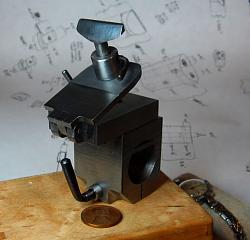
As I mentioned in my post about the t-slot base for my watchmakers lathe, the first attachment I made to fit it was a t-rest (graver rest), for turning using a hand-held graver.
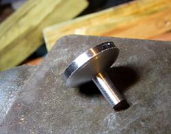
I started by turning a pin to fit the t-slot base I made previously, and cutting a couple of pieces of steel bar stock that would make up the hinged bottom section of the t-rest. The mating sides of the hinged part were quickly and roughly scraped to be a good, solid fit against one another:
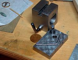
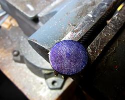
Now the tricky part, locating and cross drilling the base and the t-slot pin so that it could be locked in place with a small lever with an eccentric cam. I started by drilling the hole to fit the body of the t-slit pin. Then I put the pin into the t-slot of the mounting base, and wedged it so that it was firm against the top of the t-slot. Now the t-slot base, with the pin still wedged into it, was clamped onto the bottom plate of the t-rest, with the pin going through that hole I had drilled for it, and that bottom plate was cross drilled right through the middle of the t-slot pin and into the other side of the plate. This gave me an arrangement that would bind the pin in the t-slot nicely with an eccentric recessed lobe turned into a locking shaft of the same diameter as the hole. In theory. Well, in practice something went a bit wrong and I ended up gradually opening up the hole to get the final fit I wanted. Here are the parts, after achieving a good locking fit:
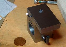
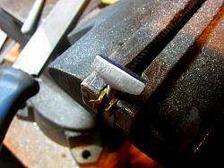
That thinner plate, to act as the top of the hinged arrangement, needed to have a lug attached to it. The lug needed to fit into a notch milled into the lower, thicker plate, then a pin put through them to pivot. I started by clamping them together, and milling a notch through both of them. Then I silver soldered a rectangular lug into the top notch. The next photo I took was after reassembling them with the snug fit of the lug keeping them located against one another, and then milling the sides to true everything up:
Here is a better view of the lug, before being hinged:
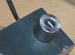
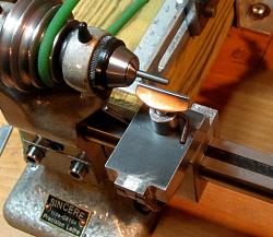
The corners were then milled out, and the resulting "ears" were cross drilled with the lug in place, the bottom of the lug and the tops of the ears were rounded for clearance, and then a brass pin pushed through. The top plate was also drilled at one end, and a steel bushing pressed in place, that would receive the actual "T" part of the rest:
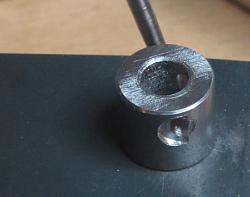
Here is a closeup of the off-center hole that was milled through the t-rest post:
Continued in the next post...


 LinkBack URL
 About LinkBacks





 Reply With Quote





Bookmarks