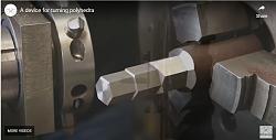
Jon recently posted a video ( Polygonal turning tool - video ) showing the method of turning polygons, multi-sided shapes, on a lathe using a rotating cutter. This was new to me but a quick internet search showed that it was a well known technique applicable for home hobbyists with limited facilities, as the video shows, as well as commercial users and is even used on CNC lathes. Even with CNC it is faster than some other methods such as indexed milling. metric-taper added to Jon's post with another homemade effort, albeit more complex. Here is a sample image of that

To satisfy my curiosity I needed to understand the mathematics behind this bit of magic. Internet searches came up with absolutely nothing. So I had to derive the expressions myself. I was expecting some complex geometry to solve but the reality is that the mathematics are very simple. I then prepared a design and understanding tool in the form of a spreadsheet to draw the shapes that could be made and that can be downloaded from https://diqn32j8nouaz.cloudfront.net...on_turning.xls.
I have also prepared a PDF file which gives a full explanation of how this method works and that can be downloaded from
https://diqn32j8nouaz.cloudfront.net...on_turning.pdf
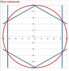
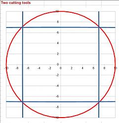
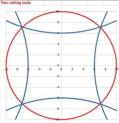
Here are some sample images from the spreadsheet:

Click for full size images.
On the left is a hexagon formed with a gear ratio of 2 and 3 cutters on the cutting shaft. Workpiece and cutters rotating in the same direction.
On the right we see a gear ratio of 3, 1 cutter and opposite sense rotation.

Both of these 4 sided shapes are cut with a 2:1 gear ratio with 2 cutters, the only difference is the sense of the rotation, same sense on the left and opposite sense on the right.
The spreadsheet is a useful design tool for anyone using this turning technique, read the PDF and it will become crystal clear. For those who want the full story the derivation of the simple mathematics is included.
Of course we need the obligatory video, just 50 seconds of Youtube shorts, this shows a slow animated simulation which clearly demonstrates the interactions between the cutting edges and the workpiece, resulting in a near straight surface. The parameters of the simulation were a gear ratio of 2:1, the cutter radius was double the workpiece radius, rotation was same sense and one cutting edge. In reality this would cut a two sided figure but the simulation is limited to one.


 LinkBack URL
 About LinkBacks


 Reply With Quote


Bookmarks