Free 186 More Best Homemade Tools eBook:  
Get tool plans

User Tag List

Page 2 of 2 FirstFirst 1 2
Results 11 to 19 of 19

Thread: Treadmill Motor

  1. #11
    Supporting Member Crusty's Avatar
    Join Date
    May 2019
    Location
    Dry Gulch, Tx
    Posts
    749
    Thanks
    220
    Thanked 854 Times in 325 Posts

    Crusty's Tools
    Yup the choke is in series. When current first passes through it some of that energy goes into building a magnetic field in the choke core until it can build no more. When the voltage to the choke is reduced, the magnetic field in the core collapses, in turn generating current in the windings. So, in a circuit it has an overall effect of smoothing out varying incoming voltage (if the choke is chosen specifically for the electrical operating conditions).

    A transformer from a microwave oven usually has enough meat in the core to make useful inductors (chokes). I'm adding DC to my Horror Freight transformer welder and I'm using as many turns of welding cable as I can get into the core to smooth the voltage ripple. Since they're wound for reasonably high current at 120V input they can also be used to make a custom transformer by winding a new secondary. Determine how many turns are in the primary then divide by 120 to arrive at the turns per volt for that transformer, then use that figure to determine how many turns are needed for your desired output voltage, then wind a secondary with that number of turns of magnet wire selected to handle your desired output current. If it fits you're crusin' on easy street.

    186 More Best Homemade Tools eBook
    Last edited by Crusty; Aug 13, 2019 at 11:35 AM.
    If you can't make it precise make it adjustable.

  2. #12
    Supporting Member olderdan's Avatar
    Join Date
    Jun 2016
    Posts
    793
    Thanks
    1,463
    Thanked 1,585 Times in 470 Posts

    olderdan's Tools
    Thanks for that Tony, I have just acquired a treadmill for parts and your clear explanation will help me a lot, I was beginning to get a bit confused with all the recent discussions.

    2,000+ Tool Plans

  3. #13
    Supporting Member
    Join Date
    Sep 2018
    Location
    Groningen, NL
    Posts
    44
    Thanks
    322
    Thanked 32 Times in 11 Posts

    Carnel's Tools
    nhengineer, for a working schematic the detailed motor and choke specifications are needed. And also with these, after building a prototype, a test is a must with enough safety measures as to avoid frying the motor, choke and electronics. Tony's suggestion of using a Pulse Width Modulated (PWM) regulator is a good choice. The motor is 2 1/2 HP (net mechanical output?) which equals about 1850 Watt. At 130V the current will be approximately 18A. For PWM control you need a power supply delivering a smooth 130V DC voltage at this current without generating a lot of grid pollution. So a well designed switch mode power supply is needed. The best thing is to achieve the supply and regulator which was used in the original treadmill.... Engineering is not always simple ;-)).

  4. #14
    Supporting Member nhengineer's Avatar
    Join Date
    Aug 2016
    Posts
    187
    Thanks
    10
    Thanked 65 Times in 37 Posts

    nhengineer's Tools
    Quote Originally Posted by tonyfoale View Post
    Others have commented on the current smoothing effects of a series choke and parallel capacitors for voltage smoothing and arc suppression so i will not go into that again.
    i just want to point out an aspect that I have never seen mentioned and which depends on the use to which the motor will be put. Many applications do not require perfectly smooth velocity over a revolution, these include tools like a drill press and lathe for example. However, if you want to drive a grinding wheel and achieve great results then you need the motor to spin as close to constant speed during a revolution as possible. If you use an SCR or thyristor controller then at less than full speed you will have a very spikey supply which requires a lot of smoothing. On the other hand if you use a PWM controller then the higher carrier frequency will be much easier to filter and you will need a much smaller choke with minimum iron in it. Of course a PWM controller is also fine for a drill or lathe.
    So why are SCR controllers used at these power levels? It is simpler older technology and until relatively recently was cheaper, but nowadays PWM controllers are cheap enough so I see no reason to not use one.
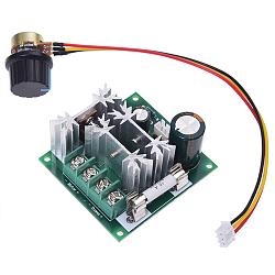
    Treadmill Motor-pmw-e08f2a5755833b5b.jpg

    This PMW baby eBay (90VDC output) is around $7. Do I still need a choke for a lathe drive?

  5. #15
    Supporting Member tonyfoale's Avatar
    Join Date
    Nov 2016
    Location
    Spain
    Posts
    1,607
    Thanks
    721
    Thanked 2,706 Times in 726 Posts

    tonyfoale's Tools
    Quote Originally Posted by Carnel View Post
    The best thing is to achieve the supply and regulator which was used in the original treadmill...
    That is the easiest but I would dispute that it is the best. Treadmill controllers have various features included which are there for safety in that application. Features like slow runup and slowdown to prevent shooting the runner off the end. There are other features as well, suited to that application. These features make the original controller somewhat less than the best for workshop tools.

  6. #16
    Supporting Member tonyfoale's Avatar
    Join Date
    Nov 2016
    Location
    Spain
    Posts
    1,607
    Thanks
    721
    Thanked 2,706 Times in 726 Posts

    tonyfoale's Tools
    Quote Originally Posted by nhengineer View Post
    Click image for larger version. 

Name:	PMW-e08f2a5755833b5b.jpg 
Views:	164 
Size:	144.0 KB 
ID:	30702

    This PMW baby eBay (90VDC output) is around $7. Do I still need a choke for a lathe drive?
    Is 1kW enough for your application? That type of controller will work fine on a lathe without a choke, you could use one but NOT the same type as you would use for an SCR control. The core in those would be too lossy for the 15kHz carrier frequency and would absorb power and heat up.

    In previous questions on this theme I have pointed out another potential problem with using variable speed motors on workshop machinery. it is a question of simple physics.
    If you run at reduced speed with some form of mechanical gearing then the available spindle torque will increase in proportion to the motor:spindle speed ratio. On most machine tools you generally need more torque at slower speeds because you are dealing with larger or harder material (why else would you be running slower). If you have a single gear ratio with a variable speed motor then the spindle torque will remain approximately constant over the speed range. In other words at slower motor and spindle speeds the torque will not be multiplied as it is with mechanical speed change methods.

    The answer to this is to use a well oversize motor. I replaced a 1 hp motor on my mill with a 5 hp, and a 2 hp on the lathe with a 5.5 hp. Even with that I could detect much lower torque at very low speeds on the lathe. That is no problem for me because the nature of my work does not require that characteristic. My advice before involving yourself in the effort of fitting up a motor and control system is to carefully review your working requirements regarding torque and speed. A 1 kW motor on a lathe does not give you much torque margin for low speeds. A motor rated 1 kW at say 3000 rpm will only be able to deliver around 100 W at 300 rpm. If your work does not require high torque at low speed then you should be OK, otherwise you may be disappointed. A lathe is probably the hardest of all common workshop machines to get working well with these motors, unless it is a very small lathe.

  7. The Following 3 Users Say Thank You to tonyfoale For This Useful Post:

    DIYSwede (Aug 14, 2019), Frank S (Aug 14, 2019), Saltfever (Aug 27, 2019)

  8. #17
    Supporting Member nhengineer's Avatar
    Join Date
    Aug 2016
    Posts
    187
    Thanks
    10
    Thanked 65 Times in 37 Posts

    nhengineer's Tools
    Hey Tony,

    Yup, speed reducer = torque multiplier. I should have though of that but I'm working on design of a small lathe for which 2.5HP (± a bit) would be more than adequate. I'm thinking of a scaled up by a small amount Gingery design. I have a mega, WW-I vintage Monarch (11" swing X 6' bed) but the headstock slop doesn't allow for any kind of accuracy. I'd like to rebuild, hoping I live long enough, because just about everything is worn out. I need a small, semi-precision lathe to make some stuff for its big brother so big brother can make big stuff.

  9. #18
    Supporting Member tonyfoale's Avatar
    Join Date
    Nov 2016
    Location
    Spain
    Posts
    1,607
    Thanks
    721
    Thanked 2,706 Times in 726 Posts

    tonyfoale's Tools
    Quote Originally Posted by nhengineer View Post
    Hey Tony,

    Yup, speed reducer = torque multiplier. I should have though of that but I'm working on design of a small lathe for which 2.5HP (± a bit) would be more than adequate.
    If you use a 2.5 hp motor you will need at least a 2 kW controller. the one that you previously linked to was a 1 kW unit.

  10. #19
    Supporting Member nhengineer's Avatar
    Join Date
    Aug 2016
    Posts
    187
    Thanks
    10
    Thanked 65 Times in 37 Posts

    nhengineer's Tools
    Quote Originally Posted by tonyfoale View Post
    If you use a 2.5 hp motor you will need at least a 2 kW controller. the one that you previously linked to was a 1 kW unit.
    Thank you Tony!


    2,000+ Tool Plans

Thread Information

Users Browsing this Thread

There are currently 1 users browsing this thread. (0 members and 1 guests)

Bookmarks

Posting Permissions

  • You may not post new threads
  • You may not post replies
  • You may not post attachments
  • You may not edit your posts
  •