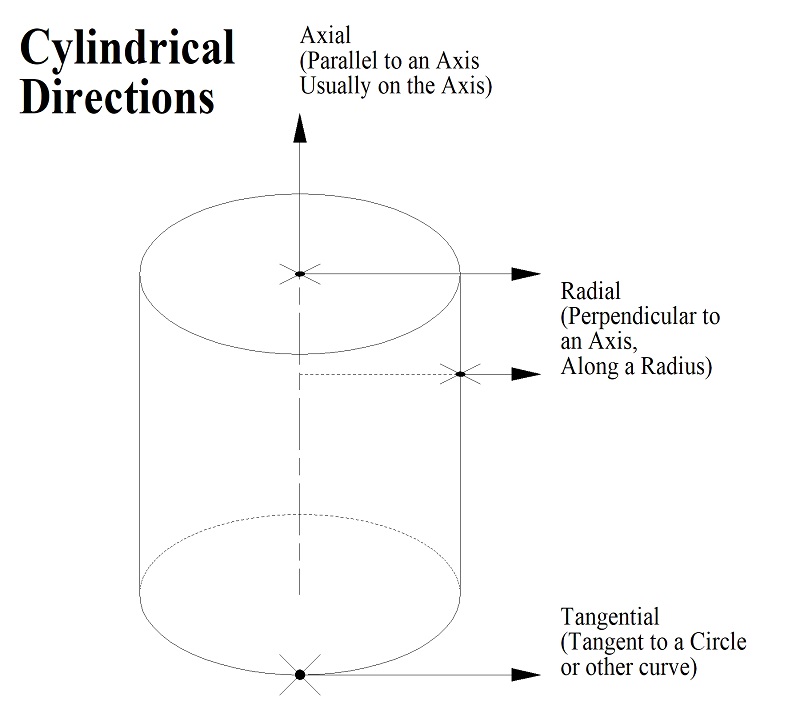
I have seen several instances where different people have used improper terms for the direction of forces or stresses in the past week or two. There is apparently some confusion over terms like "radial", "axial", and "tangential". These are three terms that can be applied to cylindrical objects, like bearings, shafts, gears, pulleys, and many other parts that are typically produced on a lathe by turning. Therefore I have produced this drawing to help show how these three terms are properly applied.
As the drawing shows, the word "axial" is the proper way to describe the direction that is parallel to an axis (of a cylinder). Therefore a thrust bearing is a way of controlling axial movement or force.
The word "radial" refers to the direction along a radius of a circle or sometimes, by extension, in a direction that is at a right angle to some central axis. Therefore a standard ball bearing is primarily designed to oppose radial movement.
The word "tangential" is used to describe a direction parallel to a circle at a point on that circle or some other curve. Therefore, when we are turning something in our lathes that part is experiencing a tangential force at the point where the tool is in contact with it. Or a pulley experiences tangential force where the belt contacts it.
When we are describing forces or directions in machines, it is important to use the correct terminology to prevent confusion. I hope this is of some help.
Additional note: The terms "radial" and "axial" are also used in describing some electronic components. The standard resistors with wire leads that are cylindrical in shape with the wires attached to the centers of the two ends are called an axial style component. This applies to capacitors, diodes, fuses, and other components that are made in this general form factor. It can also apply to components of other shapes, such as rectangular, if the wires come out from the centers of two opposite faces.
Some electrolytic capacitors are cylindrical in shape but have two wires attached on ONE end and neither of them is at the center. So they are on a radius from the center of that round end and this is referred to as a radial style component. Electrical engineers are not as particular about geometry as mechanical engineers so other capacitors that have a pair of parallel leads on one side of the package are also referred to as radial style. I guess one big reason for this is because they would be handled in a very similar manner by automatic insertion machinery: the radial style wires do not need to be bent prior to inserting them in a PCB while axial leads would. So capacitors that are flat or rectangular can also be called radial style if the two leads are on one side and come out parallel to each other. Again, other types of components (resistors, diodes, fuses, etc.) can also be referred to as radial style.
I do not think that the mechanical world shares this more general use of the terms that the electronic world uses.
I will be posting this Tip on other boards so don't be surprised if you see it somewhere else.


 LinkBack URL
 About LinkBacks


 Reply With Quote

Bookmarks