Free 186 More Best Homemade Tools eBook:  
Get tool plans

User Tag List

Results 1 to 10 of 10

Thread: Tilting Mill Table

  1. #1
    Supporting Member
    Join Date
    Feb 2015
    Location
    Prescott, AZ
    Posts
    59
    Thanks
    1
    Thanked 101 Times in 26 Posts

    Shelly142's Tools

    Tilting Mill Table

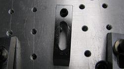
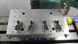
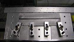
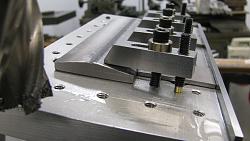
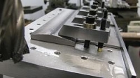
    Modified a 5” X 7” Adjustable Tilting Table by adding a Ύ” X 5” X 10” 6061-T6 Aluminum Milling Plate with Ό-20 Threaded Grid on 1” centers for clamping my work. The modification was needed to mill a taper in a 6” piece of hot rolled flat bar to be used to attach a 3’ X 5’ H.R. Plate to a steel frame for a new welding table I am working on. Also, part of the project was making the necessary clamps to hold the material securely. A steel fence was added to one edge to aid in locating (indicating) the table on the mill and the part to the table.

    Something I would like to ask the forum in regards to the clamps is why I am unable to mill a straight slot without getting a skewed slot. Generally, I end up with the slot not being straight end to end. I have tried 2 & 4 fluted cutters, chain drilling the slot to minimize the material to be removed, experimented with spindle speeds and table feeds without much improvement. Any suggestions or advice would be appreciated. The condition doesn’t affect the function but doesn’t look to good.
    Tilting Mill Table-table-milling-plate.jpgTilting Mill Table-part-taper-complete.jpgTilting Mill Table-setup-viewed-end.jpgTilting Mill Table-clamp-skewed-slot.jpg
    I had considered a couple of tilting table concepts made of aluminum plate attached to an aluminum rod and held in the vise at the required angle. The method I chose, seemed to be the best for my application.

    186 More Best Homemade Tools eBook

  2. The Following 2 Users Say Thank You to Shelly142 For This Useful Post:

    Alan Purdy (Mar 12, 2019), Tule (Mar 13, 2019)

  3. #2
    Content Editor
    Supporting Member
    DIYer's Avatar
    Join Date
    Aug 2013
    Posts
    3,055
    Thanks
    793
    Thanked 1,888 Times in 1,683 Posts


    Thanks Shelly142! We've added your Mill Table Modification to our Milling category,
    as well as to your builder page: Shelly142's Homemade Tools. Your receipt:


    2,000+ Tool Plans

  4. The Following User Says Thank You to DIYer For This Useful Post:

    mbsilvia (Mar 20, 2019)

  5. #3
    Supporting Member Toolmaker51's Avatar
    Join Date
    Feb 2016
    Location
    Midwest USA
    Posts
    5,334
    Thanks
    7,044
    Thanked 3,011 Times in 1,900 Posts

    Toolmaker51's Tools
    Not aware condition of your machine bearings/ ways/ tramming. Skewed slot can have a few causes. Appears to be full size cutter; when they dwell against 2 surfaces, the 'climbing' side pulls itself into the work. Backlash in whatever axis used is normal cause, bad bearings next in line.
    Drill ends a number or letter size larger a specific and recorded distance between centers. Use a four flute cutter at least one size smaller than desired width, calculate offset from slot center.
    [ie] A 1/2" slot: drill 33/64ths use 3/8" diameter cutter. .500 - .375 = .125/2 =.062 offset. Consider backlash when moving for the offset or use dial travel indicator.
    Sincerely,
    Toolmaker51
    ...we'll learn more by wandering than searching...

  6. The Following User Says Thank You to Toolmaker51 For This Useful Post:

    elk-a-holic (Mar 14, 2019)

  7. #4
    Supporting Member
    Join Date
    Feb 2015
    Location
    Prescott, AZ
    Posts
    59
    Thanks
    1
    Thanked 101 Times in 26 Posts

    Shelly142's Tools
    Toolmaker,
    I thank you for your input. Its possible the machine may have some backlash but I have not noticed any at this time. The machine was purchased new and is about six years old and everything appears to be pretty tight. The slot in the clamp is .250 wide and I would think if there were any significant backlash it would simply snap the Ό” end mill. The method you have suggested to correct the condition is certainly a lot more effort but if it will work that’s the way to go.
    Shelly142

  8. #5
    Supporting Member Toolmaker51's Avatar
    Join Date
    Feb 2016
    Location
    Midwest USA
    Posts
    5,334
    Thanks
    7,044
    Thanked 3,011 Times in 1,900 Posts

    Toolmaker51's Tools
    Quote Originally Posted by Shelly142 View Post
    Toolmaker,
    I thank you for your input. Its possible the machine may have some backlash but I have not noticed any at this time. The machine was purchased new and is about six years old and everything appears to be pretty tight. The slot in the clamp is .250 wide and I would think if there were any significant backlash it would simply snap the Ό” end mill. The method you have suggested to correct the condition is certainly a lot more effort but if it will work that’s the way to go.
    Shelly142
    Unless your mill has ball screw X and Y axis, there is backlash; not a leadscrew on the planet without. You can test it easily with something nicely finished like 1-2-3 blocks and an indicator. A rough estimate observes how many thousandths the dial rotates before the indicator shows movement; set indicator with leadscrew wound at least one full turn CCW (or CW) and test by carefully reversing the screw.

    in reference to slotting
    Not so much more work, it alters the process steps. 1] After sawing, mark one corner with felt tip or paint pen. 2] Attach a reference stop so each part is started and eventually reloaded same orientation. A handful in an afternoon or a hundred over several days; they'll come out far more consistently. c] Center drill one hole in each (first coordinate). d] Drill first hole, piloted if desired. e] Move axis X or Y to next coordinate. e] Repeat [c] and [d] at that location.
    Last edited by Toolmaker51; Mar 12, 2019 at 04:45 PM.
    Sincerely,
    Toolmaker51
    ...we'll learn more by wandering than searching...

  9. #6
    Supporting Member
    Join Date
    Feb 2015
    Location
    Prescott, AZ
    Posts
    59
    Thanks
    1
    Thanked 101 Times in 26 Posts

    Shelly142's Tools
    Toolmaker51
    Haven’t had a chance to actually measure how much backlash is actually in the table but I am very interested in finding out what it might be.

    I don’t plan on making any replacements for the 4 clamps shown in the photo’s as they function well enough and did do the job as intended. They just don’t look as nice as I think they should. I do appreciate your input and I certainly will make a note of your suggested process. I’m sure there will be a big improvement in any additional or new requirement clamps made in the future.

    Thank You
    Shelly142

  10. The Following User Says Thank You to Shelly142 For This Useful Post:

    Toolmaker51 (Mar 13, 2019)

  11. #7
    Supporting Member
    Join Date
    Aug 2016
    Posts
    635
    Thanks
    1
    Thanked 187 Times in 166 Posts

    wizard69's Tools
    Toolmaker covered some good points, I have a few more suugestions.

    First off lock the ways on the axis that isn’t moving.

    Check the adjustment of all Gibbs. Gibbs will break in after a bit of use and generally are loose from the factory.

    Make sure you vise is trammed and remains trammed.

  12. #8
    Supporting Member
    Join Date
    Feb 2015
    Location
    Prescott, AZ
    Posts
    59
    Thanks
    1
    Thanked 101 Times in 26 Posts

    Shelly142's Tools
    Wizard69,

    Sorry for the long delay in responding.

    The table locks are always engaged on the axis that is not in motion, something I learned a long time ago, but thanks for the reminder.

    I checked all the Gibbs and made some very minor adjustments and maybe that will also help.

    I don’t think tramming of the vise had any impact on this condition. I would think that would just produce a crooked or skewed slot or cut and be noticeable on the very first pass.

    I thank you for your guidance and suggestions.

    Shelly142

  13. The Following User Says Thank You to Shelly142 For This Useful Post:

    warsztatOdZera (Mar 28, 2019)

  14. #9
    Supporting Member warsztatOdZera's Avatar
    Join Date
    Mar 2019
    Posts
    67
    Thanks
    54
    Thanked 416 Times in 57 Posts

    warsztatOdZera's Tools
    Very nice!

  15. #10
    Supporting Member
    Join Date
    Feb 2015
    Location
    Prescott, AZ
    Posts
    59
    Thanks
    1
    Thanked 101 Times in 26 Posts

    Shelly142's Tools
    warsztat0dZera,
    Thank You, positive comments are always welcomed.
    Shelly142


    2,000+ Tool Plans

Thread Information

Users Browsing this Thread

There are currently 1 users browsing this thread. (0 members and 1 guests)

Bookmarks

Posting Permissions

  • You may not post new threads
  • You may not post replies
  • You may not post attachments
  • You may not edit your posts
  •