Free 186 More Best Homemade Tools eBook:  
Get tool plans

User Tag List

Page 1 of 4 1 2 3 4 LastLast
Results 1 to 10 of 34

Thread: Surface plate height gauge adapter for dial indicator holding

  1. #1
    Supporting Member metric_taper's Avatar
    Join Date
    Mar 2017
    Location
    Marion, Iowa
    Posts
    607
    Thanks
    237
    Thanked 265 Times in 160 Posts

    metric_taper's Tools

    Surface plate height gauge adapter for dial indicator holding

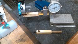
    To make the height gauge hold a dial indicator, I used some 7/16" square brass stock I had. I made one for 3/8" stems, and another for 8mm stem.
    The screw on the end is 10-32. So to finish this, I need to make some brass thumb screws. These fit in place of the carbide tipped scribe.
    I didn't see this posted by anyone, which I was hoping to see for a better design.

    Surface plate height gauge adapter for dial indicator holding-2017-04-07-puchincas-003.jpgSurface plate height gauge adapter for dial indicator holding-2017-04-07-puchincas-007.jpg

    186 More Best Homemade Tools eBook

  2. The Following User Says Thank You to metric_taper For This Useful Post:

    Paul Jones (Apr 11, 2017)

  3. #2
    Supporting Member tonyfoale's Avatar
    Join Date
    Nov 2016
    Location
    Spain
    Posts
    1,606
    Thanks
    720
    Thanked 2,703 Times in 726 Posts

    tonyfoale's Tools
    Quote Originally Posted by metric_taper View Post
    To make the height gauge hold a dial indicator, ........
    I didn't see this posted by anyone, which I was hoping to see for a better design.
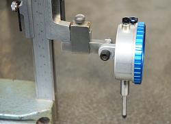
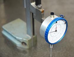
    I make no claims that mine is better but it is different to yours and I think somewhat quicker to make. It has a bit more flexibility in that you can turn the gauge such that the plunger is horizontal. There are times when that can be useful.

    Surface plate height gauge adapter for dial indicator holding-gauge-height-01.jpg
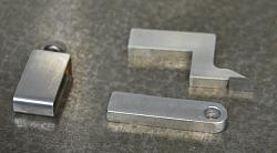
    Here is the holding piece, some rectangular bar with a single hole and rounded end.

    Surface plate height gauge adapter for dial indicator holding-gauge-height-02.jpg Surface plate height gauge adapter for dial indicator holding-gauge-height-03.jpg
    The assembly.

    2,000+ Tool Plans

  4. The Following 2 Users Say Thank You to tonyfoale For This Useful Post:

    olderdan (Apr 13, 2017), Paul Jones (Apr 11, 2017)

  5. #3
    Supporting Member mklotz's Avatar
    Join Date
    Aug 2015
    Location
    LA, CA, USA
    Posts
    3,521
    Thanks
    362
    Thanked 6,555 Times in 2,159 Posts

    mklotz's Tools
    One of the most useful height gauge accessories I've made is the skinny probe...

    http://www.homemadetools.net/forum/h...ge-probe-27844

    for measuring down in holes where the supplied gauge probe won't fit.

    It would be a simple addition to either of the holders described above. Simply drill a hole and thread it for a rod or fit a setscrew to secure an unthreaded rod.
    ---
    Regards, Marv

    Experience is always far worse than pessimism

  6. The Following User Says Thank You to mklotz For This Useful Post:

    Paul Jones (Apr 11, 2017)

  7. #4
    Supporting Member metric_taper's Avatar
    Join Date
    Mar 2017
    Location
    Marion, Iowa
    Posts
    607
    Thanks
    237
    Thanked 265 Times in 160 Posts

    metric_taper's Tools
    Quote Originally Posted by tonyfoale View Post
    I make no claims that mine is better but it is different to yours and I think somewhat quicker to make. It has a bit more flexibility in that you can turn the gauge such that the plunger is horizontal. There are times when that can be useful.
    Tony:
    Thanks, that exactly what I was hoping for was different ideas on modifications to a surface plate height gage. I didn't think of the lug mount. I've been machining for 40+ years, but only recently have gotten into surface plate usage and measurements. My metrology tools are still limited. I don't have a cylindrical square, or precision compound angle plate yet. I'm thinking at $180 for a 3x6 inch cylindrical, I would attempt to make one on the lathe, and tool post grind the final surface cut. So far the measurement needs were for a tapered sleeve, so a sine plate, Jo blocks, and bench center were the first surface plate "furniture" I purchased.

  8. #5
    Supporting Member metric_taper's Avatar
    Join Date
    Mar 2017
    Location
    Marion, Iowa
    Posts
    607
    Thanks
    237
    Thanked 265 Times in 160 Posts

    metric_taper's Tools
    Quote Originally Posted by mklotz View Post
    One of the most useful height gauge accessories I've made is the skinny probe...

    http://www.homemadetools.net/forum/h...ge-probe-27844

    for measuring down in holes where the supplied gauge probe won't fit.

    It would be a simple addition to either of the holders described above. Simply drill a hole and thread it for a rod or fit a setscrew to secure an unthreaded rod.
    Marv:
    Thanks, that is another tool to make for the height gage. "Playing" on the surface plate is a new hobby direction. So I'm still in learn mode with using it to make parts measurements. Up till now, the only 'tenths' measurements were for ball bearing press fits. I let the machine (and my setup) do it's best for square and parallel. Which has not been a problem until I ran into one on the lathe. Namely the sleeve in the headstock that reduces what was thought to be a 6MT (per the manual), to the 4MT center. Pretty sure it's a DIN 90mm gauge line 20:1 metric taper. 6MT is about 1" smaller diameter (7MT is too small as well), so I have no idea what the China manufacture draftsman was trying to describe. I recently purchased a Federal dial indicator ADG1 size that is small enough to fit inside the spindle bore. I verified the 20:1 taper (off by 0.01mm per 40mm, and I need to cross check with another indicator to validate it does not have error). I also learned the import indicator mag holders I had were horrible at dealing with the small spring forces of the indicator (when cantilevered out 6 inches). So I just got a Noga, WOW. Again, my dial indicator measurements were really only runout on the lathe, I think this was the first time I've used one for absolute measurement for a taper angle. The bottom zero adjust is a must from here on out. I thought my mag bases were OK, till I put them on the surface plate and they all rock. I guess $15-$25 is not enough for the manufacture to grind them flat. The stiffness of the Noga is really impressive.
    Thanks

  9. #6
    Supporting Member mklotz's Avatar
    Join Date
    Aug 2015
    Location
    LA, CA, USA
    Posts
    3,521
    Thanks
    362
    Thanked 6,555 Times in 2,159 Posts

    mklotz's Tools
    In addition to a DI holder you'll want to provide for a way to mount a DTI, preferably one that reads to tenths. I simply tapped a hole into the side of my holder and mounted a cross-drilled rod that accepts the DTI stem.

    My main use for the DTI is to provide repeatable measuring pressure. For example, comparing a workpiece height to a reference Jo block height... Touch off on the Jo block with the DTI tip and note the dial reading. Now touch the work in such a way as to repeat that dial reading. Then the height difference measured on the height gauge is not influenced by human ability to reproduce touch pressure accurately.

    When touching down on something it's all too easy to lift the height gauge foot slightly and thus create an erroneous reference. Using the DTI approach helps solve that problem.
    ---
    Regards, Marv

    Experience is always far worse than pessimism

  10. The Following User Says Thank You to mklotz For This Useful Post:

    cogentia (May 21, 2022)

  11. #7
    Supporting Member tonyfoale's Avatar
    Join Date
    Nov 2016
    Location
    Spain
    Posts
    1,606
    Thanks
    720
    Thanked 2,703 Times in 726 Posts

    tonyfoale's Tools
    Quote Originally Posted by metric_taper View Post
    Tony:
    Thanks, that exactly what I was hoping for was different ideas on modifications to a surface plate height gage. I didn't think of the lug mount.
    I always use the lug for mounting wherever possible. If there is no lug or other good reason to prevent its use then I use a split clamp to hold the instrument by the barrel, as in the following photos which show a clamp mounting, holding a linear encoder. Sometimes I fit a dial gauge when I don't need great accuracy or don't need to read by Laptop.
    It would only be in exceptional cases that I would ever use a screw to clamp the barrel in a hole as you have done. There are 2 reasons for this.
    1. It is the least kind method for the instrument, if tightened too much it will distort the barrel.
    2. It is the least secure method. Unless the hole is a very good fit and reasonably long the gauge is likely to wobble about destroying accuracy. This imprecise fitting encourages over-tightening of the screw.

    There are those who worry about the lack of precise vertical alignment, when using the lug, but these concerns are over exaggerated. Without much care it is easy to align the plunger to within say 0.5deg as a worst case. The effect of such misalignment is proportional to the cosine of the angular error. To put numbers to that, it means that over a movement range of 25mm the total error would be less than 1 micron for a 0.5 deg setup error. Or in other words 0.04 microns per 1mm. Way, way less than the resolution and accuracy of most any dial gauge, and also way less than the effect of minor temperature changes.
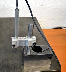
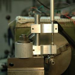
    Surface plate height gauge adapter for dial indicator holding-linear-encoder.jpg Surface plate height gauge adapter for dial indicator holding-lift-encoder-tappet.jpg
    On the left the encoder is clamped for use on a surface plate. On the right it is mounted in place of a lathe toolpost for measuring camshaft profiles. The large hole in the block is a legacy of the block's previous use. just a nice heavy piece out of the scrap box, hardened and ground on the bottom and sides so ideal for its new use.

    Here is another example of clamping on the shank that I posted a while back.
    http://www.homemadetools.net/forum/p...5372#post81710
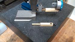
    Last edited by tonyfoale; Apr 16, 2017 at 09:48 AM. Reason: Added link to earlier post.

  12. The Following User Says Thank You to tonyfoale For This Useful Post:

    olderdan (Apr 16, 2017)

  13. #8
    Supporting Member metric_taper's Avatar
    Join Date
    Mar 2017
    Location
    Marion, Iowa
    Posts
    607
    Thanks
    237
    Thanked 265 Times in 160 Posts

    metric_taper's Tools
    Quote Originally Posted by mklotz View Post
    In addition to a DI holder you'll want to provide for a way to mount a DTI, preferably one that reads to tenths. I simply tapped a hole into the side of my holder and mounted a cross-drilled rod that accepts the DTI stem.

    My main use for the DTI is to provide repeatable measuring pressure. For example, comparing a workpiece height to a reference Jo block height... Touch off on the Jo block with the DTI tip and note the dial reading. Now touch the work in such a way as to repeat that dial reading. Then the height difference measured on the height gauge is not influenced by human ability to reproduce touch pressure accurately.

    When touching down on something it's all too easy to lift the height gauge foot slightly and thus create an erroneous reference. Using the DTI approach helps solve that problem.
    Thanks Marv.
    The next tool is a height gauge holder for the DTI. As it's apparent I need this for the stiffness when above the surface plate 12 or so inches. I recently purchase a surface gauge (used), which has a sloppy zero adjust. Seeing the 'buggered' screw head (for the hinge of the rocker), this was a problem to the previous owner. I don't know if there is a shim missing, but the rocker plate has much clearance to the machined slot this fits. It's an 'antique' of unknown maker (it does appear manufactured, with old chipped black paint on the sides). I'm of the belief now that the previous owner disassembled this and lost some shim. I Probably should buy a used Starrett. The seem to be pricey if they are complete and not rusty (eBay).

    I'll make another holder for the DTI, as I've got many feet of this square brass stock. I assume I don't need to use tool steel for this as it's a holder and not relying on a machined surface for accuracy. The main effort was to 'whittle' the end down to fit the existing clamp of the scriber, as I'm mimicking this geometry. The DTI I have, came with 2 different dovetail mounts. Seems the large one would be the one that would be held with the least compliance from 'my' machining tolerance. I'm thinking the end mount dovetail would be the best general purpose mount to accommodate. Seems this would give the best reach on a larger part.

  14. #9
    Supporting Member metric_taper's Avatar
    Join Date
    Mar 2017
    Location
    Marion, Iowa
    Posts
    607
    Thanks
    237
    Thanked 265 Times in 160 Posts

    metric_taper's Tools
    Quote Originally Posted by tonyfoale View Post
    I always use the lug for mounting wherever possible. If there is no lug or other good reason to prevent its use then I use a split clamp to hold the instrument by the barrel, as in the following photos which show a clamp mounting, holding a linear encoder. Sometimes I fit a dial gauge when I don't need great accuracy or don't need to read by Laptop.
    It would only be in exceptional cases that I would ever use a screw to clamp the barrel in a hole as you have done. There are 2 reasons for this.
    1. It is the least kind method for the instrument, if tightened too much it will distort the barrel.
    2. It is the least secure method. Unless the hole is a very good fit and reasonably long the gauge is likely to wobble about destroying accuracy. This imprecise fitting encourages over-tightening of the screw.

    There are those who worry about the lack of precise vertical alignment, when using the lug, but these concerns are over exaggerated. Without much care it is easy to align the plunger to within say 0.5deg as a worst case. The effect of such misalignment is proportional to the cosine of the angular error. To put numbers to that, it means that over a movement range of 25mm the total error would be less than 1 micron for a 0.5 deg setup error. Or in other words 0.04 microns per 1mm. Way, way less than the resolution and accuracy of most any dial gauge, and also way less than the effect of minor temperature changes.

    Click image for larger version. 

Name:	linear encoder.JPG 
Views:	726 
Size:	127.3 KB 
ID:	17483 Click image for larger version. 

Name:	lift encoder and tappet.JPG 
Views:	512 
Size:	61.7 KB 
ID:	17484
    On the left the encoder is clamped for use on a surface plate. On the right it is mounted in place of a lathe toolpost for measuring camshaft profiles. The large hole in the block is a legacy of the block's previous use. just a nice heavy piece out of the scrap box, hardened and ground on the bottom and sides so ideal for its new use.

    Here is another example of clamping on the shank that I posted a while back.
    http://www.homemadetools.net/forum/p...5372#post81710
    Thanks Tony,
    For lathe 'dialing in' the lug mount is how my current setup is.
    I'm new to surface plate work, so still in learning mode. I've not machined many split clamps (the lathe tails stock quill, and drill press spindle both for depth measurement tooling are the only ones I can think of). So small thin slits I've not done, (and I don't think I have a thin saw in my tooling). Time for eBay search.

    How accurate is the linear encoder? I'm looking for something to use on the surface grinder, as I can't trust the down feed dial.

    From looking at your piston crown thickness gauge, and your camshaft lobe metrology, you must do custom engine work needing such measurements. Is this for hobby or 'prostitution'?
    Steve

  15. #10

    Join Date
    Feb 2014
    Posts
    7
    Thanks
    5
    Thanked 2 Times in 1 Post
    Hi guys, I have found that rather than buy a cylinder square, look around for some wrist pins from a large diesel engine. They are usually hardened ,ground,and sometimes chrome plated. Better yet you can them for free!!!! BLF

  16. The Following 2 Users Say Thank You to barsyl4041@netzero.net For This Useful Post:

    Neil Jensen (Apr 17, 2017), tonyfoale (Apr 17, 2017)

Thread Information

Users Browsing this Thread

There are currently 1 users browsing this thread. (0 members and 1 guests)

Bookmarks

Posting Permissions

  • You may not post new threads
  • You may not post replies
  • You may not post attachments
  • You may not edit your posts
  •