By which is meant solid geometry,
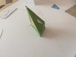
This little prism has taken me 8 hours to do, today, and it is only one quarter of what is required, at one end of a piece of wood I want to use!
About 35 years ago I saw a picture of a timber framed building under construction and what was quite intriguing was that the hip rafter was square in section, rotated so that the diagonal through was plumb. Thatís not the way Iíd been taught and I didnít know how to do it then, but I had the vague ambition of investigating it one day.
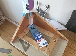
This is the start. On the basis that I will learn more if it is more than usually complicated, there are two unequal planes. So the hip rafter, which is what I am working on here, is inclined to the post at 34 degrees on plan. The two sides are 36 degrees and about 26 degrees respectiveLy and meet together at the junction of the hip with the post.
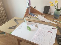
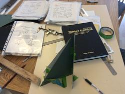
There has been such a plethora of lines and points, so many elevations to rabat, that I stopped using geometry, and have been using trigonometry. The data is over a page and a quarter of A4, and thatís without some of the jottings. Projecting the points lead to creeping inconsistencies. Also, picking compasses up and putting them down , I rarely find the radius is the same when I next want it. Digital callipers and winged dividers I find are more reliable.
And with all the lines on the board, I found the best way of avoiding confusion is to make overlays. Some of them are stuck to the model, some a stuck to the boards, some are lying about on the floor and a lot are in the bin.
The only way to speed up is by practice, if Iím spared!


 LinkBack URL
 About LinkBacks


 Reply With Quote


Bookmarks