Still playing around with non-circular boring/turning... Added some math to add a radius to the corners so the change in direction isn't as abrupt..


Big-Pete (Oct 7, 2020), Carnel (Oct 6, 2020), goonergord (Oct 5, 2020), greenie (Oct 4, 2020), H.L (Oct 6, 2020), high-side (Oct 9, 2020), Home-PC (Oct 7, 2020), lassab999 (Oct 21, 2020), mwmkravchenko (Oct 5, 2020), nightride (Oct 7, 2020), olderdan (Oct 4, 2020), rdarrylb (Oct 5, 2020), rgsparber (Oct 5, 2020), Scotty12 (Oct 5, 2020), Sleykin (Oct 5, 2020), sossol (Oct 8, 2020), tonyfoale (Oct 6, 2020), Tonyg (Oct 6, 2020)
Alan, That is essentially how cam grinders work but they use a grinding wheel instead of a turning tool. That is, you adjust the inward position of the grinding head in sync with the rotation of the work piece. Nowadays this is done with CNC machines but previously the control was by templates, often with oversize base circles for template accuracy.
I have made cams using the X & Y axis of a CNC mill. Maybe I'll make a separate post about that so as not to hi-jack this post.
Hi Tony, I was expecting some input from you on this. I should have said generate cams and not turn as tool geometry would be not suitable, I was thinking of using live tooling which is what you have done with your mill. Some years ago I made some model engine cams for a friend and still have the 10:1 master template. This was done the old fashioned way on the lathe with a live spindle. Home made cam grinders are many ranging from the basic to the sophisticated and I have found the Model Engineering fraternity a great source of ingenuity. Machining them is the easy bit, deciding the profile is a subject of great depth and expertise.
Home-PC (Oct 16, 2020)
Home-PC (Oct 16, 2020)
Alan,
Machining/grinding cams can be the easy bit depending on the level of accuracy needed. Nowadays, OEM car and bike manufacturers make cams to quite incredible accuracy to ensure smooth and quiet running. Top end performance applications also demand very high standards for life and performance. In the performance field multi-lobe cams often have the cam profiles angularly offset to account for twist in the shaft. Some also have slightly different profiles for each cylinder to optimise for differences in temperature, and mixture strength between cylinders.
The old hotrodders' trick of grinding the base circle to get more lift just does not cut it these days at the top end, although it is still practised by some old school cam grinders.
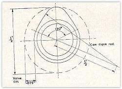
As you say designing the profile is the tricky bit, both for performance reasons and mechanical reasons. You can design a cam to get air into the cylinder but mechanically the profile might induce valve train destroying vibrations due to excessive acceleration and jerk. Even if those parameters are in the acceptable range there may be harmonic vibrations in the rest of the valve train. That is less of a problem with non-pushrod engines. The design of cams for low speed and/or model engines is generally less critical and people get away with what might be regarded as poor design, such as joining a base and top circle with a simple curve as per your illustration. Having said that, probably millions of cams have been built that way and worked well enough in non-critical applications.
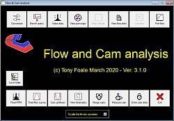
I have developed some cam design and analysis software which will calculate the optimal mechanical profile from required performance parameters. Even then I do a dynamic analysis of the whole valve train before being happy with it. There are some very Q&D videos here
https://www.youtube.com/playlist?lis...SvlfD6C_oAHYK3

Kinda cheated and made the component so it could scan in a gcode shape.... Now I should be able to bore or turn any shape (within reason of tooling..)
Have not tested on actual hardware yet..
The right shape is the gcode - left is the spindle synced motion. With and without cutter offset. (obviously wouldn't be boring a cam shape usually - but it is easier to visualize..)

Home-PC (Oct 16, 2020)
This was my first attempt using X-Y movements without work-piece rotation. That was using a 16 mm tool. Subsequent efforts were even better because I used a huge diameter tool, i.e. a grinding wheel. The greater tool size meant that the centre had a much longer path to follow and so the same linear increments resulted in finer angular increments.
Click for full size

Last edited by tonyfoale; Oct 18, 2020 at 05:13 PM.
olderdan (Oct 19, 2020)
There are currently 1 users browsing this thread. (0 members and 1 guests)
Bookmarks