

 LinkBack URL
 About LinkBacks


I began this adventure as a test to see if I could figure out where the Lathe Chuck Center was in relation to the Ways.
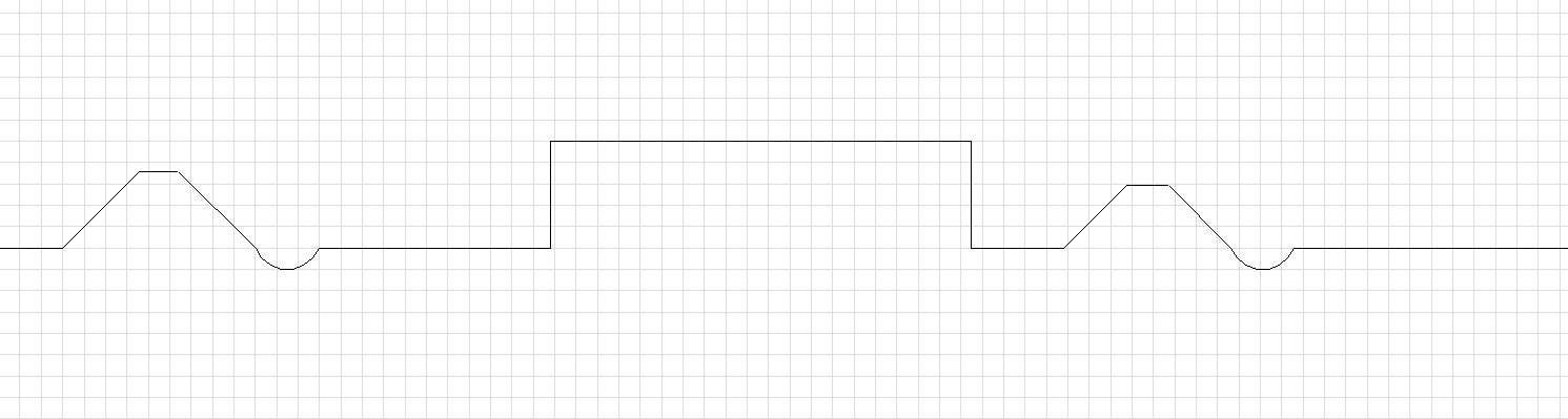
My goal is to build a fixture to let me get the three jaw or four jaw chuck off/on without having to juggle the chuck and the tools. I've seen ones made of wood, but my first attempt to make a wooden one was not successful -- and even though I vacuumed the wood, I still dropped sawdust onto the ways and oil. I learned during that adventure that while the Flats on the Ways were parallel and level to each other, the inverted Vs are not. The profile of my lathe's ways looks approximately like this:
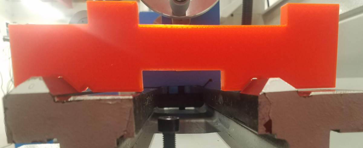
Left and Right inverted Vs have different profiles and I just couldn't repeatably measure. My third attempt at printing the profile (measure then print then test then rinse and repeat) got me pretty close but not really:
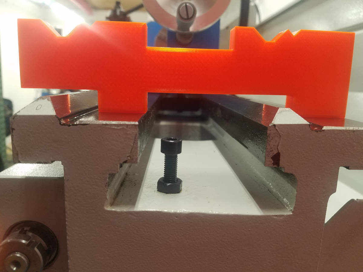
You can see the gaps above the flats, really difficult to measure when the things you are measuring are not referenced to the same thing. I did think ahead a little and printed just the flats with clearance for the non-flats so I could at least see if the flats were parallel and level to each other:
Now I could reference something! I chose the flat nearest the operator and I would just ignore the inverted Vs, my fixture didn't need them.
So now how to figure out where the chuck is. For that, well, its easy - the chuck and the tail stock are relative to each other and if I put a center in the tail, the tip would be the center of chuck. (NOTE: it is supposed to be made this way.)
The reference point is now known, so how do we measure to that tip in space? I tried 123 blocks, parallels, squares, and I didn't get the two dimensions to measure the same way after I set it up different ways to try to make sure it would be close and repeatable ... no joy ... now for something completely different...
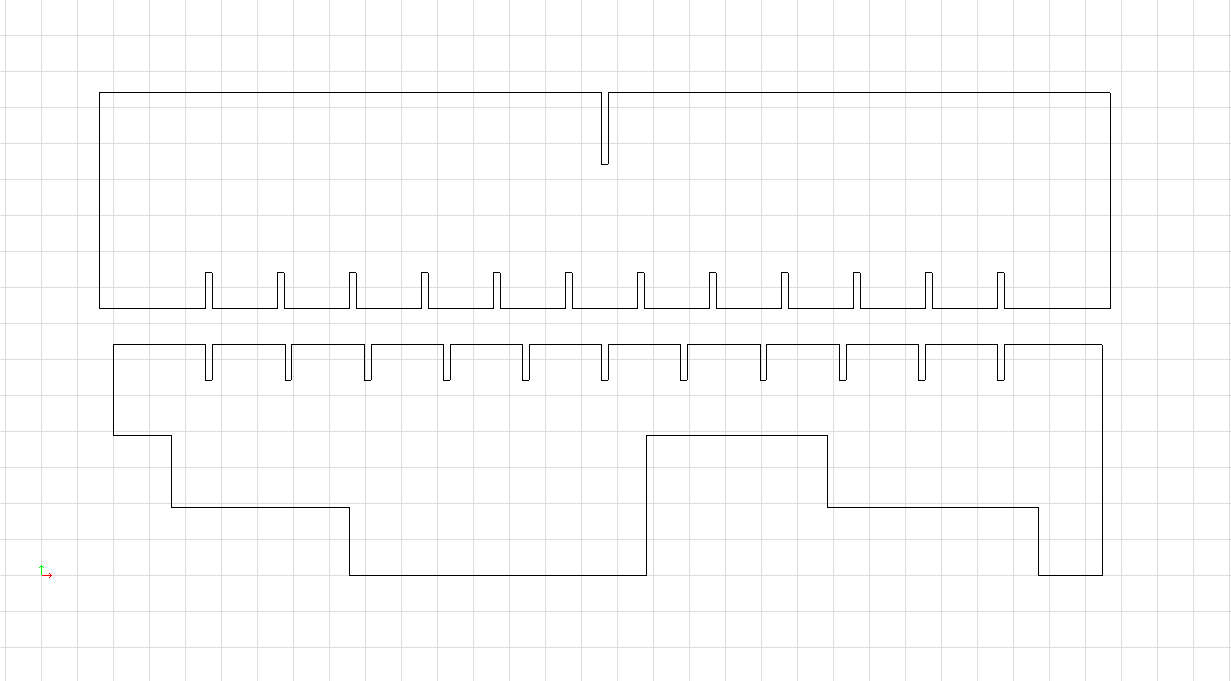
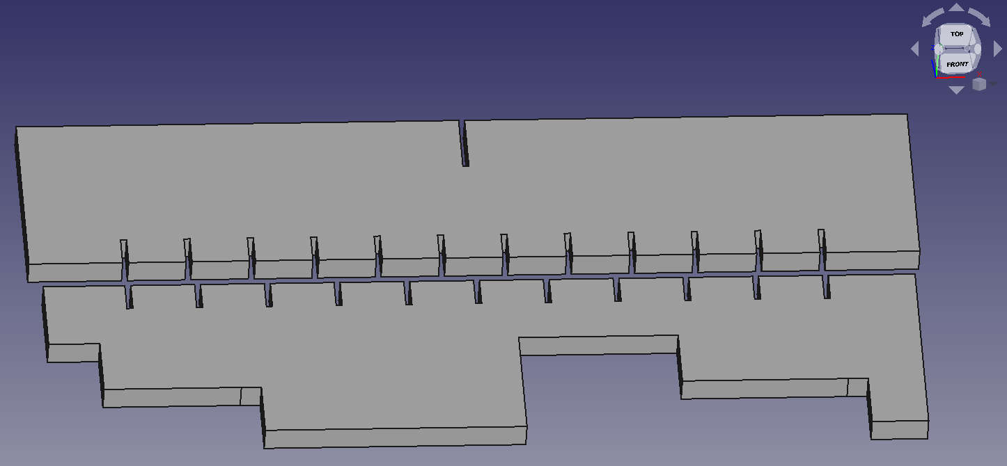
I decided to put my 3D printer to work. I knew my printer was pretty consistent and very reliable and I often print a test piece to see if I got the measurements right (remember those pieces above?) so why not here? I could make a close enough measurement of the tip from the top of the flat (actually with the 123 block stack and some parallels going across, I got it really close). I could use the vertical on the flat to align a 123 block to that edge so I could translate that point nearer to the thing I am trying to measure. All of that led me to make a drawing of this:
There are two pieces here. The bottom is the one that rests on the flats (or rather the 123 blocks on the flats). The top piece is to slide back and forth on the bottom piece and it gets aligned to the tip of the center. Notice that there are slots in both pieces, but they are not aligned except on the left and right side of the drawing. These are drawn as a Vernier scale. The slot is 1.2mm wide which is 3 times the 0.4mm printer extrusion width. The bottom piece has one extra slot over the same distance in the pieces. Here it is in FreeCAD after extrusion:
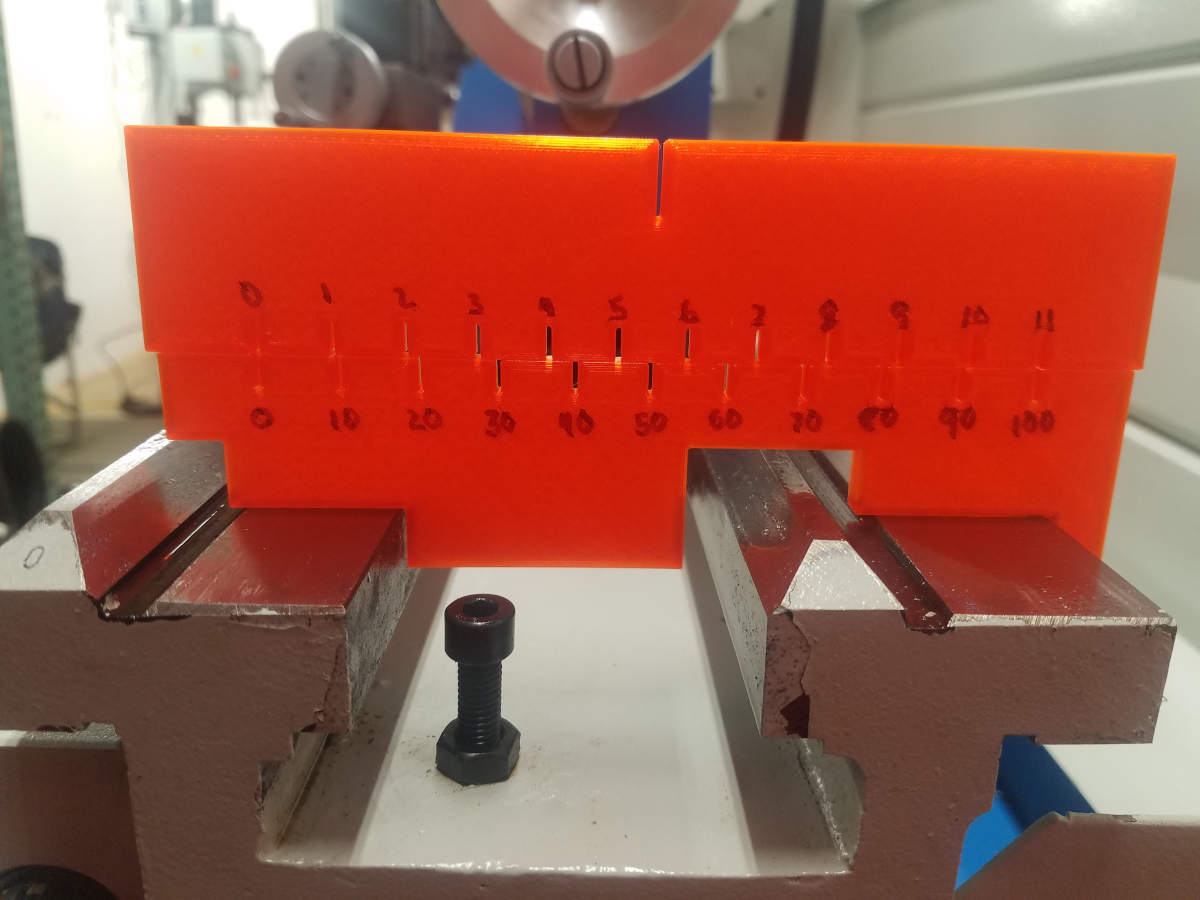
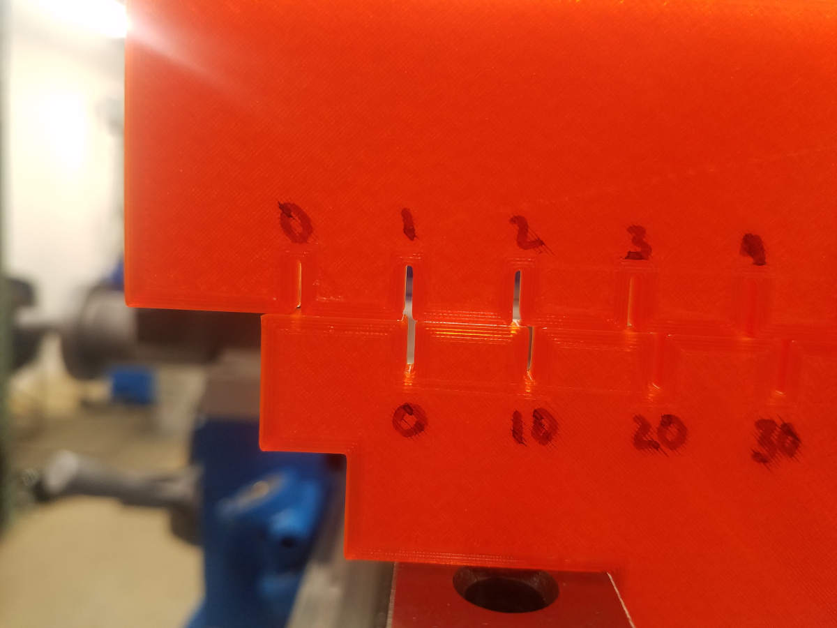
Then printed and marked so I could know what was which was where:
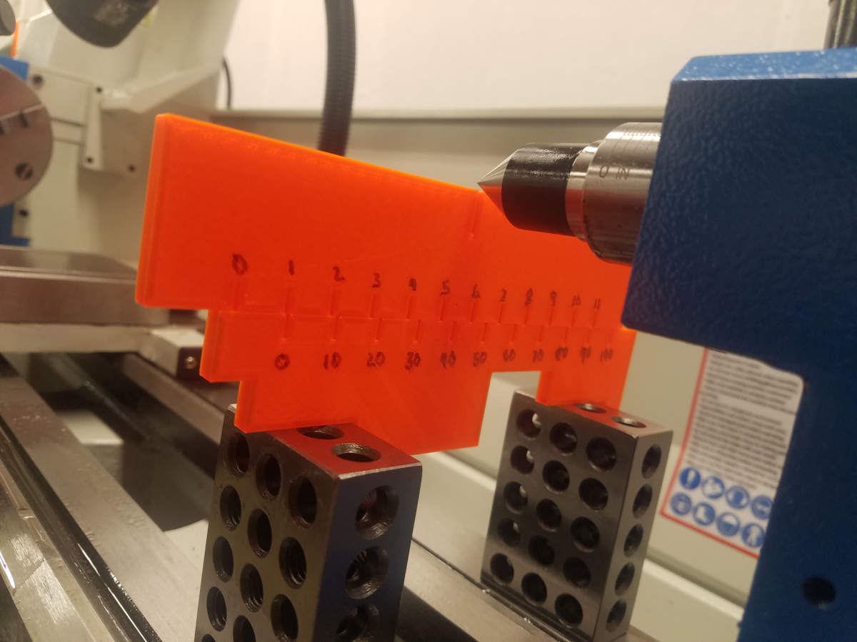
Now add the 123 blocks and align the flat and align the tip:
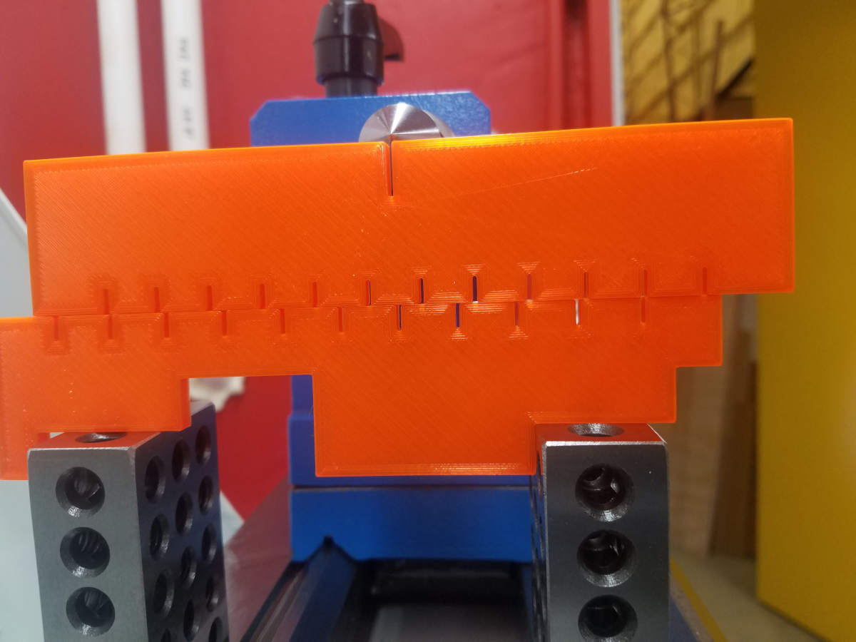
We can see that there is a different alignment from the drawing to the actual and we can use that difference to figure out the distance. From the other side it looks like this:
And a close-up so we can see the overlap:
The 1 slot is shifted about 1/3 the space of the bottom 0 slot - which magically is an easy 1/3 of 1.2mm or 0.4mm. Can I use this to be the way to calculate the answer? Well no, because I need to go back to the drawing because I don't know the distance from the flat reference to the 0 slot of the bottom and I don't know the distance from the top piece top slot to any of its bottom slots. Also note, I didn't say what the slot to slot spacing was for either the upper or lower slots.
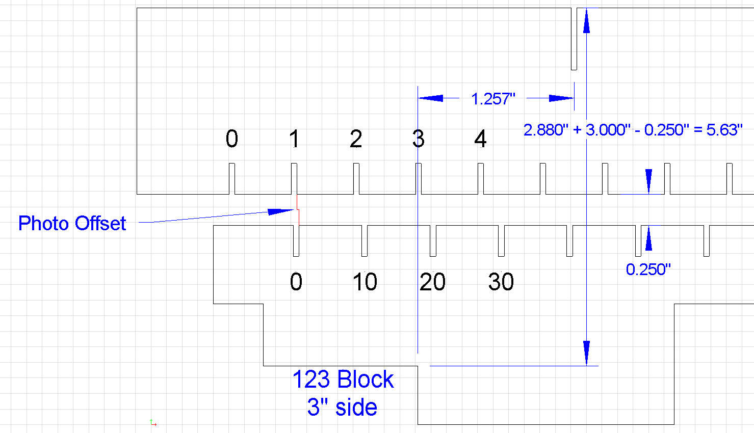
But, I don't care. I just need the reference from the picture and I can modify the cad drawing to figure it out. In the cad drawing, I created a line which was the Photo Offset, then shifted the top piece to match the line end, and then dimensioned the flat reference point to the center of the top piece slot:
That last 3D print was, according to Cura, $1.01 cost, which was way, way less than the amount of time I spent trying to figure out how to make the measurement.


 Reply With Quote


Bookmarks