The last post I submitted was a tool known as an Angle Dresser, an Angle Dresser is for shaping any angle on the side of a grinding wheel for grinding machines by means of a diamond nib, I had mentioned in that post that I was in the middle of making a new tool (I didn’t say what it was) and ran into a setup problem finishing that tool so it had to be put on the back burner until I made a tool to complete it with, and that’s why I had to make the Angle Dresser, (man that was a mouth full) Now that the Angle Dresser has been completed I can continue making the tool I was making before I made the Angle Dresser, I hope I made all that clear.
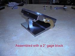
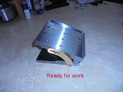
Working with precision angles can be a little problematic to setup like anything else if you don’t have the right tools, without the right tools it takes longer and it probably didn’t come out as well as you wanted it to but you settled for it anyway, I have made quite a few angle plates for quick setups in the mill vice or for whatever reason, I wanted to make a tool that I could setup angles quickly and this is why the Sine Plate was designed and built.
I have always used a Sine Bar, Tool Makers Vice, Dial Indicator, Gage Blocks and a Surface Plate to perform these setups making angle plates before which worked fine butwas a time consuming process, now I will be able to set the Sine Plate to any angle I want using the required amount of gage blocks then mount the tool makers vice on the Sine Plate and grind away, although a magnetic sine plate would have beennice.
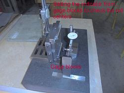
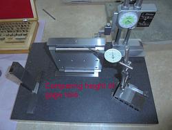
Sine plates are very simple in design yet a very high degree of precision has to be applied to the manufacturing process of this sort of tool to achieve precision end results, not just this Sine Plate was made that precisely but all the precision tools I make are checked from a Granite SurfacePlate using a Tenth Indicator, Gage Blocks and a Cylinder Square making sure everything to be flat, parallel and square within .0002” - .0003”
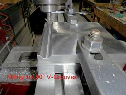
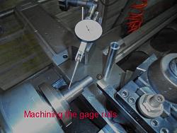
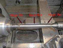
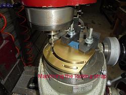
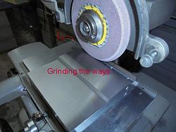
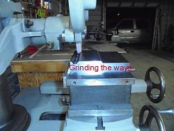
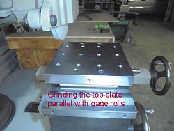
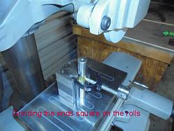
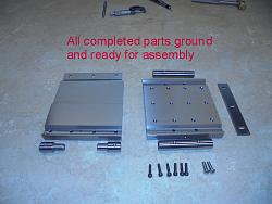
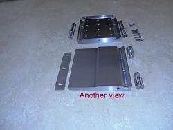
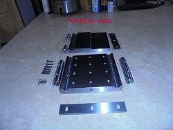
The upper and lower plates of this tool were made from 3/4” 4140 pre hard steel, the rolls were made from 3/4” round 4140 TG&P pre-hardened steel, the locking strap was made from 1/4” thick 360 brass flat stock and the two side rails were made from 3/16” X 1” 4140 precision ground flat stock, all surfaces and edges were precision ground flat, parallel and square, the 90° V-Grooves that precisely locate the gage rolls were probably the most time consuming to grind, I made several trips back and forth from the surface grinder to the surface plate before I got the 5” center distance on the rolls perfect, I could only grind one side of the 90° v-groove at a time due to the width of my grinding wheel, a 1” wide wheel with a 45° dressed on both sides would have been the answer but I can only put a maximum 3/4" wide wheel on the machines spindle, always some little something isn’t there?
All and all everything came out great, looks good and functions perfectly.
This tool would be a challenge to make even for the experienced tool maker.
Below are some photos of the machining and grinding processes of making this tool.
As always thanks for looking
And happy machining
Doug


 LinkBack URL
 About LinkBacks



 Reply With Quote


Bookmarks