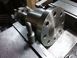
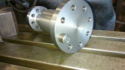
Made 2 pair of drive axles, very short couplings between motor an apparatus, larger bolt circle is the motor end.
To simplify installation, I desired the bolt circles should clock, be same orientation, starting at 12 o'clock position.
If there are 3 cardinal rules for machinery - form, fit, function; they interchange as to which should be #1, each application is different. This case favors the mechanics.
This part, roughly 3.7 Ø at one end 4.9 Ø at the other, flanges about .62" thick. Overall length mounted on the indexer to tall for knee mill, flange kind of narrow for drilling horizontally indexed. Doing 4 pcs though, made a repeating setup worthwhile.
Hmmm, as I look over available tooling. Shape of axle has all the diameters concentric, a good datum; but flanges being different mean re-centering.

Hmmm, indeed.
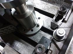
Here's a big Vee-Block. Futzing around, determined height above table spacers [1-2-3's this time] would position on larger middle part with either flange up or down.
I can divide the bolt pattern by Jig Bore Coordinates, or the DRO function; I usually prefer coordinates. Getting started, I center/ pilot/ size drilled and chamfered large end bolt circle in each of the four.
For the patterns to coincide took three steps.
1] Made a pin, slip-fit 10mm and .630 Ø, for the table slot.

2] Dialed in center of Tee-Slot.
3] With pin in one hole, then in T-slot, then parked in the Vee-Block; moved Vee-Block around to clock the smaller flange in, without changing X axis.
Clamped lower flange to table and finished the parts. Used coordinates for the smaller bolt circle in 12 o'clock initial position. Jig Bore Coordinates can be found in earlier Machinists Handbooks. Basic application of trig tables for a specific number of holes multiplied by any desired bolt circle.


 LinkBack URL
 About LinkBacks


 Reply With Quote

Bookmarks