Free 186 More Best Homemade Tools eBook:  
Get tool plans

User Tag List

Results 1 to 4 of 4

Thread: Home made powered knee lift on milling machine.

  1. #1
    Supporting Member tonyfoale's Avatar
    Join Date
    Nov 2016
    Location
    Spain
    Posts
    1,611
    Thanks
    726
    Thanked 2,721 Times in 728 Posts

    tonyfoale's Tools

    Home made powered knee lift on milling machine.

    I previously asked about commercially made powered knee lifters in the post Z axis power feed advice sought

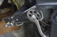
    I decided to power the Z knee axis as discussed. I had enough bits and pieces on the shelf so I decided to make my own. I thought that it would probably be just as quick to do that as fit a commercially made one.

    Home made powered knee lift on milling machine.-dsc_0012.jpg Click for full size.

    When I bought my mill it had been fitted as a CNC machine from new but with it I also scored a spare set of servo motors and all the gubbins for mounting, including belts and pulleys etc. So it was just a question of bolting the motor mounting plate to the knee and fitting the motor and belt. The mounting plate (13 mm aluminium) already had the motor mounting slots, so it was an easy and quick job. I added a two way switch to set direction, up or down, and a momentary button switch to activate.

    Home made powered knee lift on milling machine.-dsc_1399.jpg Home made powered knee lift on milling machine.-dsc_1401.jpg

    It worked but it really struggled. Then I did something that I should have done in the beginning. I measured the torque needed to wind the crank. It was higher than the motor and its gearing was rated for. I decided to replace it with a bought one but before I placed the order I came across a camshaft pulley that I had saved off an old car. It had 42 teeth in place of the one that I had fitted of 26. That would give a near 62% increase in torque. I was confident that would be enough to transform a working device that struggled into one that was adequate for the job. Even if the motor was a bit highly stressed its duty cycle will be very low. A few seconds use followed by an hour, week or month of rest. The teeth had the same pitch as the belt and lower small pulley but the tooth form did not match exactly. I considered the likely number of hours use that it would see in its life time and decided not to worry.

    Home made powered knee lift on milling machine.-dsc_6050.jpg

    I wanted to keep the ability to use the original crank and with pure luck the sleeve that the castellated drive piece was connected to was a perfect fit in the hole of the pulley. So that saved making any sleeves for fitting the new pulley.

    Home made powered knee lift on milling machine.-dsc_6049.jpg

    The larger pulley did not fit inside the original safety belt cover and I modified it to suit. Firstly I added a piece to the mounting plate, a bit larger than the new pulley, upon which to fit a modified cover.

    Home made powered knee lift on milling machine.-dsc_6051.jpg Home made powered knee lift on milling machine.-dsc_6056.jpg

    The larger pulley dictated that the motor be moved closer to the top pulley to retain the original belt, as shown below.

    Home made powered knee lift on milling machine.-dsc_6052.jpg Home made powered knee lift on milling machine.-dsc_0002.jpg

    I cut the sides of the cover such that I could bend them around the new piece on the mounting plate. I cut the flat part of the cover along the line at the top of the photo and cut out a replacement piece to suit the new shape and welded it together

    Home made powered knee lift on milling machine.-dsc_6054.jpg Home made powered knee lift on milling machine.-dsc_6053.jpg Home made powered knee lift on milling machine.-dsc_0006.jpg

    The cover can be pivoted about the lower two mounting screws when all the others are removed. This allows for belt tension setting and gives access to the electrical connections to the switches, without having to disconnect the switches to remove the cover.

    Home made powered knee lift on milling machine.-dsc_0009.jpg

    The next photo shows how the manual winding crank still fits if needed.

    Home made powered knee lift on milling machine.-dsc_0003.jpg

    I am pleased to report that the revamped powered winder is totally successful. It works as it should, it moves quite fast and makes life easier for a geriatric.

    Note about winding torque. As mentioned above I measured that torque but I also did some calculations to estimate if the values tied up with the physics. Knowing the weight of the knee assembly with saddle and table, and that one revolution of the handle lifts the knee 0.1” it is easy to calculate the winder torque needed just to lift the knee. Much to my surprise it was a very small fraction of the torque that I measured. The rest had to be friction. The friction is impossible to calculate with the same precision as the pure lifting force needed because it is necessary to guess many factors such as the coefficient of friction.
    Anyway using guessed friction coefficient for the lifting screw it became obvious that most of the friction was due to the acme thread and it overwhelmed the force needed for lifting the weight. Friction on the vertical ways is even harder to estimate, one reason is that the load on the ways depends on the CG position of the total knee assembly and that varies depending of the weight of vices, work pieces etc and the X-Y position of the table. There should be one position for a given loading arrangement where there is no load on the ways but even then there is friction force due to imperfections and shearing of lubricant.
    It was clear that most of the input torque required is due to the lifting screw friction so the replacement of the ACME lift screw with a ball screw would remove a lot of the motivation to fit a powered feed.
    Download plans for milling tools.

  2. The Following 10 Users Say Thank You to tonyfoale For This Useful Post:

    biggist (Today), ductape (Nov 24, 2024), emu roo (Nov 26, 2024), flyfr8rs (Today), Inner (Nov 26, 2024), Jon (Yesterday), michaelmacnz (Nov 27, 2024), mwmkravchenko (Today), Ralphxyz (Nov 26, 2024), Sleykin (Nov 26, 2024)

  3. #2
    Content Editor
    Supporting Member
    DIYer's Avatar
    Join Date
    Aug 2013
    Posts
    3,055
    Thanks
    793
    Thanked 1,891 Times in 1,686 Posts


    Thanks tonyfoale! We've added your Powered Knee Lift to our Milling category,
    as well as to your builder page: tonyfoale's Homemade Tools. Your receipt:


    Download plans for milling tools.

  4. The Following User Says Thank You to DIYer For This Useful Post:

    tonyfoale (Nov 26, 2024)

  5. #3
    Supporting Member
    Join Date
    Feb 2015
    Posts
    151
    Thanks
    36
    Thanked 96 Times in 44 Posts

    Manitoba Man's Tools

    Power Knee

    Quote Originally Posted by tonyfoale View Post
    I previously asked about commercially made powered knee lifters in the post Z axis power feed advice sought

    I decided to power the Z knee axis as discussed. I had enough bits and pieces on the shelf so I decided to make my own. I thought that it would probably be just as quick to do that as fit a commercially made one.

    Click image for larger version. 

Name:	DSC_0012.JPG 
Views:	82 
Size:	653.4 KB 
ID:	48397 Click for full size.

    When I bought my mill it had been fitted as a CNC machine from new but with it I also scored a spare set of servo motors and all the gubbins for mounting, including belts and pulleys etc. So it was just a question of bolting the motor mounting plate to the knee and fitting the motor and belt. The mounting plate (13 mm aluminium) already had the motor mounting slots, so it was an easy and quick job. I added a two way switch to set direction, up or down, and a momentary button switch to activate.

    Click image for larger version. 

Name:	DSC_1399.JPG 
Views:	44 
Size:	246.2 KB 
ID:	48398 Click image for larger version. 

Name:	DSC_1401.JPG 
Views:	44 
Size:	733.2 KB 
ID:	48399

    It worked but it really struggled. Then I did something that I should have done in the beginning. I measured the torque needed to wind the crank. It was higher than the motor and its gearing was rated for. I decided to replace it with a bought one but before I placed the order I came across a camshaft pulley that I had saved off an old car. It had 42 teeth in place of the one that I had fitted of 26. That would give a near 62% increase in torque. I was confident that would be enough to transform a working device that struggled into one that was adequate for the job. Even if the motor was a bit highly stressed its duty cycle will be very low. A few seconds use followed by an hour, week or month of rest. The teeth had the same pitch as the belt and lower small pulley but the tooth form did not match exactly. I considered the likely number of hours use that it would see in its life time and decided not to worry.

    Click image for larger version. 

Name:	DSC_6050.JPG 
Views:	35 
Size:	1.36 MB 
ID:	48400

    I wanted to keep the ability to use the original crank and with pure luck the sleeve that the castellated drive piece was connected to was a perfect fit in the hole of the pulley. So that saved making any sleeves for fitting the new pulley.

    Click image for larger version. 

Name:	DSC_6049.JPG 
Views:	34 
Size:	1.66 MB 
ID:	48401

    The larger pulley did not fit inside the original safety belt cover and I modified it to suit. Firstly I added a piece to the mounting plate, a bit larger than the new pulley, upon which to fit a modified cover.

    Click image for larger version. 

Name:	DSC_6051.JPG 
Views:	30 
Size:	1.64 MB 
ID:	48402 Click image for larger version. 

Name:	DSC_6056.JPG 
Views:	31 
Size:	646.1 KB 
ID:	48403

    The larger pulley dictated that the motor be moved closer to the top pulley to retain the original belt, as shown below.

    Click image for larger version. 

Name:	DSC_6052.JPG 
Views:	27 
Size:	1.83 MB 
ID:	48404 Click image for larger version. 

Name:	DSC_0002.JPG 
Views:	33 
Size:	567.6 KB 
ID:	48405

    I cut the sides of the cover such that I could bend them around the new piece on the mounting plate. I cut the flat part of the cover along the line at the top of the photo and cut out a replacement piece to suit the new shape and welded it together

    Click image for larger version. 

Name:	DSC_6054.JPG 
Views:	26 
Size:	1.62 MB 
ID:	48410 Click image for larger version. 

Name:	DSC_6053.JPG 
Views:	26 
Size:	2.24 MB 
ID:	48406 Click image for larger version. 

Name:	DSC_0006.JPG 
Views:	30 
Size:	440.9 KB 
ID:	48407

    The cover can be pivoted about the lower two mounting screws when all the others are removed. This allows for belt tension setting and gives access to the electrical connections to the switches, without having to disconnect the switches to remove the cover.

    Click image for larger version. 

Name:	DSC_0009.JPG 
Views:	36 
Size:	648.1 KB 
ID:	48408

    The next photo shows how the manual winding crank still fits if needed.

    Click image for larger version. 

Name:	DSC_0003.JPG 
Views:	40 
Size:	604.0 KB 
ID:	48409

    I am pleased to report that the revamped powered winder is totally successful. It works as it should, it moves quite fast and makes life easier for a geriatric.

    Note about winding torque. As mentioned above I measured that torque but I also did some calculations to estimate if the values tied up with the physics. Knowing the weight of the knee assembly with saddle and table, and that one revolution of the handle lifts the knee 0.1” it is easy to calculate the winder torque needed just to lift the knee. Much to my surprise it was a very small fraction of the torque that I measured. The rest had to be friction. The friction is impossible to calculate with the same precision as the pure lifting force needed because it is necessary to guess many factors such as the coefficient of friction.
    Anyway using guessed friction coefficient for the lifting screw it became obvious that most of the friction was due to the acme thread and it overwhelmed the force needed for lifting the weight. Friction on the vertical ways is even harder to estimate, one reason is that the load on the ways depends on the CG position of the total knee assembly and that varies depending of the weight of vices, work pieces etc and the X-Y position of the table. There should be one position for a given loading arrangement where there is no load on the ways but even then there is friction force due to imperfections and shearing of lubricant.
    It was clear that most of the input torque required is due to the lifting screw friction so the replacement of the ACME lift screw with a ball screw would remove a lot of the motivation to fit a powered feed.
    Great work and thinking behind it, as we have come to expect. Excellent explanation as well. Thanks Mr. Foale

    Bob B.
    Manitoba, Canada

  6. The Following User Says Thank You to Manitoba Man For This Useful Post:

    tonyfoale (Today)

  7. #4
    Supporting Member
    Join Date
    Aug 2021
    Location
    Cape Town SA
    Posts
    232
    Thanks
    728
    Thanked 84 Times in 38 Posts

    albertq's Tools
    Nice one Tony. If you use it often as I use mine, you'll wonder why you hadn't done it long ago. It's a necessary luxury to have.


    Download plans for milling tools.

Thread Information

Users Browsing this Thread

There are currently 10 users browsing this thread. (1 members and 9 guests)

  1. tonyfoale

Tags for this Thread

Bookmarks

Posting Permissions

  • You may not post new threads
  • You may not post replies
  • You may not post attachments
  • You may not edit your posts
  •