Free 186 More Best Homemade Tools eBook:  
Get tool plans

User Tag List

Page 1 of 2 1 2 LastLast
Results 1 to 10 of 20

Thread: Screw-on chuck mounting to bayonet.

  1. #1
    Supporting Member tonyfoale's Avatar
    Join Date
    Nov 2016
    Location
    Spain
    Posts
    1,609
    Thanks
    722
    Thanked 2,707 Times in 727 Posts

    tonyfoale's Tools

    Screw-on chuck mounting to bayonet.

    Screw-on chuck mounting to bayonet.-chuck_mtg_02.jpg Click thumbnails for fullsize.

    Name:  Arrow.JPG
Views: 3140
Size:  3.7 KB

    Screw-on chuck mounting to bayonet.-chuck_mtg_10.jpg

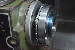
    I bought my first lathe when I was about 16, it was a Myford Super 7. A great little lathe but I hated the screw-on chuck mounting and I have hated them since. After owning my current Jet lathe for over ten years I have finally got around to doing something about it.

    My favourite chuck mounting is what is known as a long nose taper. The long taper provides the drive from spindle to chuck, it has a key which ensures that the chuck is always fitted with the same angular location and the chuck is held to the spindle by means of a large threaded sleeve which is also used to force the chuck off the spindle. The length of the taper means that the chuck back plate has to be quite long, I had four chucks and a face plate to fit and that would have required making a whole lot of swarf.

    My second choice would be what is known as a "D" Camlock fitting. These have a short taper and a very quick system of holding the chuck onto it using a chuck style key. However, there would have been a lot of work to make the adaption to fit the existing screw on spindle. I was sure that there would be commercial conversion kits available but I drew a blank.

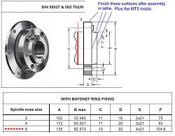
    Some years ago I had a very old and worn lathe which had a "bayonet" chuck fitting. This was the best part of the lathe. When I scrapped it I kept a chuck backplate and a face plate. The standard for this type of mounting has mounting dimensions very similar to the "D" type and the mounting and removal is fairly quick and easy. My existing chuck back plates only needed a bit of boring out and drilling and tapping for four studs. I already had a suitable back plate for one chuck so I only had three to do. The following video shows how I did it. It was very easy and I am over the moon with the result. I find myself changing chucks more often, instead of using a 3 jaw with a shim I now simply switch to a 4 jaw when more appropriate.


    There is an excellent listing of chuck mounting methods with dimensions at https://www.smalltools.com/lathe-spi...ication-chart/
    Here is a section showing details of different sizes of bayonet mounting.
    Screw-on chuck mounting to bayonet.-chuck_mtg_64.jpg
    Download plans for chucks.

  2. The Following 13 Users Say Thank You to tonyfoale For This Useful Post:

    asterix (Feb 15, 2021), Carnel (Feb 16, 2021), DIYSwede (Feb 15, 2021), johncg (Feb 16, 2021), Jon (Feb 15, 2021), Little Rabbit (Feb 15, 2021), mwmkravchenko (Feb 16, 2021), nova_robotics (Feb 21, 2021), olderdan (Feb 15, 2021), old_toolmaker (Feb 15, 2021), rebuilder1954 (Feb 16, 2021), sacco1 (Feb 15, 2021), Saltfever (Feb 22, 2021)

  3. #2
    Supporting Member DIYSwede's Avatar
    Join Date
    May 2019
    Location
    Stockholm, Sweden...
    Posts
    634
    Thanks
    417
    Thanked 805 Times in 319 Posts

    DIYSwede's Tools
    -At last! Excellent job and easy-to-follow video, Tony!
    Smart time- & materials saving move to use all-thread for the 20 studs.

    -I seem to remember: -Weren't the new spindle bearings intended to be of the angular contact type?
    These seem to be tapered roller bearings. Any comment on preloading these?

    ATB
    Johan
    Download plans for chucks.

  4. #3
    Supporting Member tonyfoale's Avatar
    Join Date
    Nov 2016
    Location
    Spain
    Posts
    1,609
    Thanks
    722
    Thanked 2,707 Times in 727 Posts

    tonyfoale's Tools
    Quote Originally Posted by DIYSwede View Post
    -
    These seem to be tapered roller bearings. Any comment on preloading these?
    Johan
    Difficult to get right.
    There is not enough thickness of material to put a pair of angular contact bearings at the sharp end. I would need to line bore the head and insert a sleeve all the way through. It is doable, but would be too much work/time.

  5. The Following User Says Thank You to tonyfoale For This Useful Post:

    DIYSwede (Feb 16, 2021)

  6. #4

    Join Date
    Jul 2020
    Posts
    11
    Thanks
    122
    Thanked 0 Times in 0 Posts
    I have the same problem type lathe, you have done a Excellent job with the conversion ,I suppose you would not nip over and do mine,Great Job.

  7. #5
    Supporting Member Toolmaker51's Avatar
    Join Date
    Feb 2016
    Location
    Midwest USA
    Posts
    5,334
    Thanks
    7,044
    Thanked 3,012 Times in 1,901 Posts

    Toolmaker51's Tools
    Quote Originally Posted by sacco1 View Post
    I have the same problem type lathe, you have done a Excellent job with the conversion ,I suppose you would not nip over and do mine,Great Job.
    Rofl: "Nip over...". He's either nearby or other half of the planet? He'd be certainly be a terrific visitor!

    I'm jealous regarding Bayonet mount system; completely unfamiliar to me. Still shot of vid told me "aaha, converting to short taper A1 or A2."
    Nope, not even close. we share no pity for threaded spindles. Not even complimentary on indexers etc. I've had a milling cutter impart enough leverage causing a chuck loosening, while climbing a transverse slot.
    The bayonet carries benefits akin A1, A2, D, and L. The biggest to me, is split but accomplished simultaneously, positive drive and positive orientation. A's, Bayonet and L get that built-in with the drive boss [A's and Bayonet] or key [L's]. D requires a step you undertake personally. The cam pins impart positive drive, but there is no feature returning to same bores they are initially set for. Yet I remain D-mount fan in lathes they are appropriate, which get pretty big.
    Mark the chuck plate and spindle, a paint mark is sufficient. A chuck will take a stamp, most spindles hardened beyond range a stamp can penetrate. I feel assured when each cam is marked as well, indicating engagement.

    Larger machines seem to depend on retention bolts of "A", where operating the spanner for "L", or Tee handle for "D" is pure gymnastics. Same machines rarely if ever have the chuck removed, as faceplate and jaws are combined.
    But that bayonet!
    https://www.smalltools.com/lathe-spi...ication-chart/
    It's missing from this US version chart. It may be more common for European users.
    Last edited by Toolmaker51; Feb 15, 2021 at 09:17 PM.
    Sincerely,
    Toolmaker51
    ...we'll learn more by wandering than searching...

  8. #6
    Supporting Member
    Join Date
    Oct 2019
    Posts
    4
    Thanks
    1
    Thanked 1 Time in 1 Post
    FYI I've been looking to make an adapter to allow my D1-4 chucks to be mounted on a rotary table. One of the first thing I noticed was that 7 1/8 degree taper. I suppose it is well know by all here, but I found that tan(7 1/8 deg) ~ 1/8 which greatly simplifies the necessary calculations.

  9. #7
    Supporting Member Toolmaker51's Avatar
    Join Date
    Feb 2016
    Location
    Midwest USA
    Posts
    5,334
    Thanks
    7,044
    Thanked 3,012 Times in 1,901 Posts

    Toolmaker51's Tools
    Quote Originally Posted by stephanb View Post
    FYI I've been looking to make an adapter to allow my D1-4 chucks to be mounted on a rotary table. One of the first thing I noticed was that 7 1/8 degree taper. I suppose it is well know by all here, but I found that tan(7 1/8 deg) ~ 1/8 which greatly simplifies the necessary calculations.
    If I was to apply D1 chuck to a rotary table, I'd make a large enough diameter for common strap clamps or plain studs, with a short boss on the back side for the table bore. Morse taper is common place. Loose or close fit will simplify dialing in, recommend against slip fit.

    Alternately, a suitable bore on the locating table if you intend leaving the pins in place. I foresee difficulty removing chuck against gravity, compared with hanging on a spindle.
    Last edited by Toolmaker51; Feb 15, 2021 at 09:52 PM. Reason: umm, that I haven't in awhile?
    Sincerely,
    Toolmaker51
    ...we'll learn more by wandering than searching...

  10. The Following User Says Thank You to Toolmaker51 For This Useful Post:

    stephanb (Feb 15, 2021)

  11. #8
    Supporting Member tonyfoale's Avatar
    Join Date
    Nov 2016
    Location
    Spain
    Posts
    1,609
    Thanks
    722
    Thanked 2,707 Times in 727 Posts

    tonyfoale's Tools
    [QUOTE=Toolmaker51;

    I'm jealous regarding Bayonet mount system; completely unfamiliar to me. ................
    It's missing from this US version chart. It may be more common for European users.[/QUOTE]

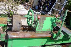
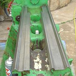
    I think that it was European. The old lathe that I had with it on was of Spanish manufacture. I have seen a reference that they were fitted up until 1975. I that the A is the common fitting for the cheaper end and D for the less cheap.
    I got that old lathe for the price of shipping. It looked to be very rusty but when I started cleaning it I realised that it was not the lathe that was rusty, it was the grinding grit that it was covered in. Apparently it had been stored where iron casting fettling was done. Within a week or so of getting it running I got a three year job offer, out of the blue, at Segway in the US. I bought my current lathe whilst in the US and so when I returned to Spain I scrapped the old lathe because the ways had a big wear dip right where it would be most used. It would have been a great lathe except for the wear, it was heavy and very rigid.

    Screw-on chuck mounting to bayonet.-aswas.jpg Screw-on chuck mounting to bayonet.-cleanways.jpg Click thumbnails for full size

  12. #9
    Supporting Member tonyfoale's Avatar
    Join Date
    Nov 2016
    Location
    Spain
    Posts
    1,609
    Thanks
    722
    Thanked 2,707 Times in 727 Posts

    tonyfoale's Tools
    Quote Originally Posted by stephanb View Post
    FYI I've been looking to make an adapter to allow my D1-4 chucks to be mounted on a rotary table. One of the first thing I noticed was that 7 1/8 degree taper. I suppose it is well know by all here, but I found that tan(7 1/8 deg) ~ 1/8 which greatly simplifies the necessary calculations.
    Most odd angle tapers come about because they are designed to a certain slope. In this case 1 in 8 probably. I suspect that the design intent was 1 in 8 and that the angle follows from that.

  13. #10
    Supporting Member Toolmaker51's Avatar
    Join Date
    Feb 2016
    Location
    Midwest USA
    Posts
    5,334
    Thanks
    7,044
    Thanked 3,012 Times in 1,901 Posts

    Toolmaker51's Tools
    Quote Originally Posted by tonyfoale View Post
    I think that it was European.......<snipped>
    It would have been a great lathe except for the wear, it was heavy and very rigid.

    Click image for larger version. 

Name:	AsWas.jpg 
Views:	184 
Size:	193.6 KB 
ID:	38501 Click image for larger version. 

Name:	CleanWays.JPG 
Views:	153 
Size:	34.8 KB 
ID:	38502 Click thumbnails for full size
    Get an eyeful of those ways, NO scrimping there!

    Later years then US heavy iron, Italy, Spain, Britain, areas around Poland, Czechoslovakia, likely Russia too, had no hesitation building heavy patterned machine castings. I'm sure the iron was of good specification like Meehanite, chilled, seasoned, induction hardened as measures of competition.
    At same time German and Swiss offerings had thinner sections but far more webbing. I'm thinking those were chasing foreign markets [shipping], the heavy stuff more domestic.
    Despite gargantuan appearance, those of Italian and central European makers operated in a very civil but positive manner. Had examined British, French and Spanish too, apparently not so many sold, never had one in front of me on a shop floor, save one HES lathe. That had wonderful collection of features, for certain.
    Sincerely,
    Toolmaker51
    ...we'll learn more by wandering than searching...

Thread Information

Users Browsing this Thread

There are currently 1 users browsing this thread. (0 members and 1 guests)

Tags for this Thread

Bookmarks

Posting Permissions

  • You may not post new threads
  • You may not post replies
  • You may not post attachments
  • You may not edit your posts
  •