Free 186 More Best Homemade Tools eBook:  
Get tool plans

User Tag List

Page 1 of 2 1 2 LastLast
Results 1 to 10 of 11

Thread: Rotation indicator + N, PE, 30 mA RCD test

  1. #1
    Supporting Member 2gsg2_muc's Avatar
    Join Date
    Aug 2021
    Location
    Munich
    Posts
    29
    Thanks
    0
    Thanked 48 Times in 16 Posts

    2gsg2_muc's Tools

    Rotation indicator + N, PE, 30 mA RCD test

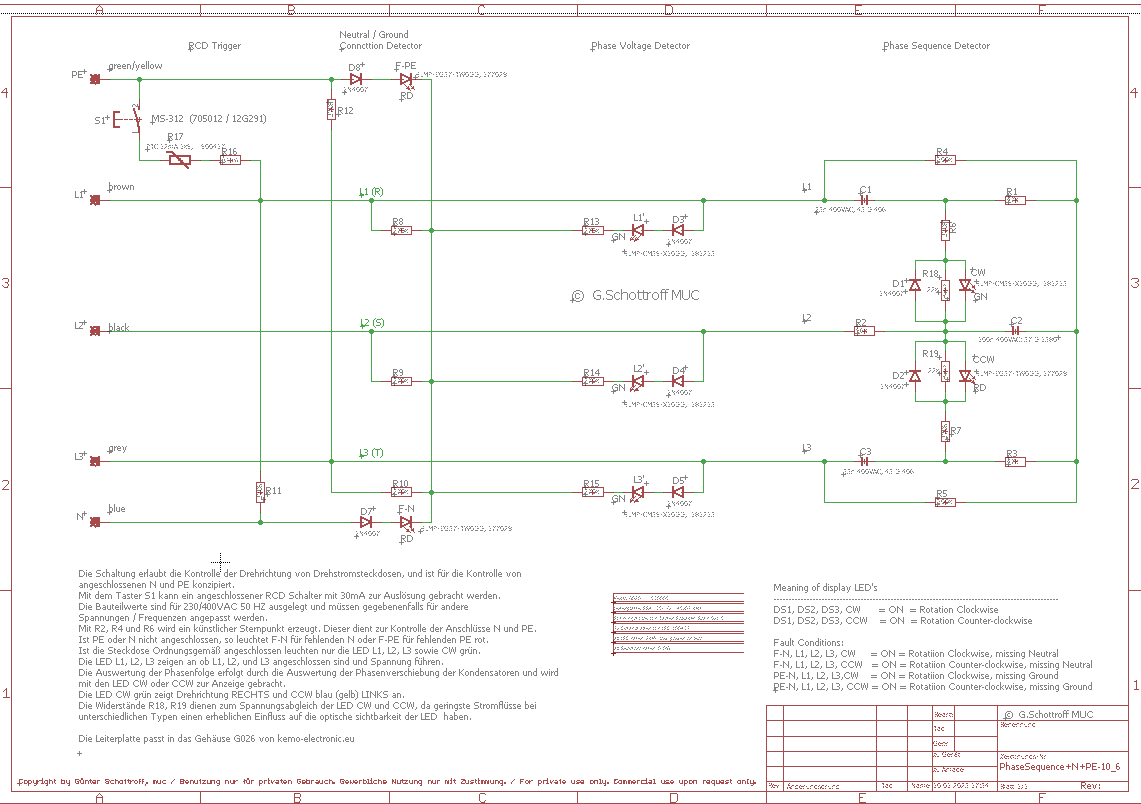
    Hallo, dies ist ein älteres Design eines 3-Phasen-Steckdosenprüfers, einschließlich Prüfung von Neutral und Grond-Ameisen-Testknopf für 30-mA-RCD. Es ist sehr nützlich und zeigt eine einfache Anzeige. Die mittlere Linie bestehend aus drei grünen LED zeigt Linien an, wenn sie leuchten. Ein grünes Dreieck mit den 3 Groundline-LEDs plus der CW-LED grün zeigt die Richtung nach rechts an. Wenn es eine grüne 3 LED-Grundlinie plus eine rote LED CCW anzeigt, ist die Richtung links. Wenn Sie also ein grünes Dreieck sehen, ist die Steckdose vollständig mit L1, L2, L3, Neutral und Masse verbunden. Jede rot leuchtende LED auf der linken oder rechten Seite in der unteren Zeile zeigt einen fehlenden Neutralleiter oder Masse an. Die mittlere rote LED zeigt die CCW-Richtung an. Zusätzlich gibt es einen Prüfschalter für RCD, durch Drücken dieser Taste wird der RCD betätigt und schaltet die Versorgung ab. Wenn keine Reaktion erfolgt, gibt es 4 Möglichkeiten, 1. RCD check function 2. RCD has higher value than 30 mA, check RCD 3. No RCD installed 4. Check Supply line


    best regards Guenter

    186 More Best Homemade Tools eBook
    Last edited by Jon; Jan 7, 2023 at 06:50 PM.

  2. The Following 3 Users Say Thank You to 2gsg2_muc For This Useful Post:

    Jon (Jan 13, 2023), nova_robotics (Jan 10, 2023), odd one (Jan 9, 2023)

  3. #2
    Supporting Member desbromilow's Avatar
    Join Date
    Aug 2012
    Location
    Australia
    Posts
    800
    Thanks
    527
    Thanked 362 Times in 207 Posts

    desbromilow's Tools
    Looks good, do you have clearer (larger) schematics - I found the image too grainy to follow in any detail. I am particularly interested to se how rotation is measured.

    2,000+ Tool Plans

  4. #3
    Supporting Member mwmkravchenko's Avatar
    Join Date
    Nov 2017
    Location
    Perth Ontario Canada
    Posts
    1,042
    Thanks
    5,252
    Thanked 394 Times in 280 Posts
    Translated:

    Hello, this is an older design of 3 phase socket tester including testing neutral and grond ant test button for 30mA RCD. It is very useful and shows a simple ad. The middle line consisting of three green LEDs indicates lines when lit. A green triangle with the 3 groundline LEDs plus the CW LED green indicates the direction to the right. If it shows a green 3 LED baseline plus a red LED CCW, the direction is left. So if you see a green triangle, the outlet is fully connected to L1, L2, L3, Neutral, and Ground. Any solid red LED on the left or right side of the bottom row indicates a missing neutral or ground. The middle red LED indicates the CCW direction. In addition, there is a test switch for RCD, pressing this button activates the RCD and switches off the supply. If there is no reaction, there are 4 possibilities, 1. RCD check function 2. RCD has higher value than 30 mA, check RCD 3. No RCD installed 4. Check Supply line


    Guenter

    Vielen Dank für einen so gut durchdachten elektrischen Tester. Können Sie einen Schaltplan posten, den wir lesen könnten? Der aufgehängte elektrische Schaltplan ist nicht lesbar.

    (Thank you for such a well thought out electrical tester. Can you post a schematic that we could be able to read? The electrical schematic posted is not legible.)


    Mark

  5. #4
    Supporting Member 2gsg2_muc's Avatar
    Join Date
    Aug 2021
    Location
    Munich
    Posts
    29
    Thanks
    0
    Thanked 48 Times in 16 Posts

    2gsg2_muc's Tools

    Schematic new


  6. #5
    Supporting Member 2gsg2_muc's Avatar
    Join Date
    Aug 2021
    Location
    Munich
    Posts
    29
    Thanks
    0
    Thanked 48 Times in 16 Posts

    2gsg2_muc's Tools

    new schematic

    Hello, that is the best I can handle myself, doing have problems to work with updated 1indows 11, sorry for some mistakes

    Name:  3-Phase-rotation-indicator.png
Views: 660
Size:  42.1 KB

  7. The Following User Says Thank You to 2gsg2_muc For This Useful Post:

    mwmkravchenko (Jan 18, 2023)

  8. #6
    Supporting Member 2gsg2_muc's Avatar
    Join Date
    Aug 2021
    Location
    Munich
    Posts
    29
    Thanks
    0
    Thanked 48 Times in 16 Posts

    2gsg2_muc's Tools
    Hi Desbromilow

    The rotation is meassured using 2 capacitors for phase shifting powering the LED for left or rightrotation.
    Last edited by 2gsg2_muc; Jan 10, 2023 at 03:25 PM.

  9. #7
    Supporting Member desbromilow's Avatar
    Join Date
    Aug 2012
    Location
    Australia
    Posts
    800
    Thanks
    527
    Thanked 362 Times in 207 Posts

    desbromilow's Tools
    Quote Originally Posted by 2gsg2_muc View Post
    Hi Desbromilow

    The rotation is meassured using 2 capacitors for phase shifting powering the LED for left or rightrotation.
    Thankyou!!!

  10. #8
    Content Editor
    Supporting Member
    DIYer's Avatar
    Join Date
    Aug 2013
    Posts
    3,055
    Thanks
    793
    Thanked 1,885 Times in 1,682 Posts


    Thanks 2gsg2_muc! We've added your Socket Tester to our Electrical category,
    as well as to your builder page: 2gsg2_muc's Homemade Tools. Your receipt:


  11. #9
    Supporting Member metric_taper's Avatar
    Join Date
    Mar 2017
    Location
    Marion, Iowa
    Posts
    607
    Thanks
    237
    Thanked 265 Times in 160 Posts

    metric_taper's Tools
    Thank you for the readable schematic. However the resistance and capacitance values are not readable.

  12. #10
    Supporting Member 2gsg2_muc's Avatar
    Join Date
    Aug 2021
    Location
    Munich
    Posts
    29
    Thanks
    0
    Thanked 48 Times in 16 Posts

    2gsg2_muc's Tools
    Bill of Materials:

    Partlist of Outlet Tester circuit, designed for 230VAC

    Part Value Package

    ...2 FR4, 1.5mm, 35u, 2lagen, Lötstop

    ..1 2x Abstandsbolzen M3 / 18H2456 / 8 mm

    ..2 2x Schraube DIN933 M3x25 mm

    ..3 2x Stiftschraube M3x16

    ..4 7x Distanzhalter LED 20mm 18 H 518

    ..5 Recommended LED type above 2000 mcd Resistor value for R7, R8, R9, R10, R11, R12, R15
    depending on type of used LED at 10 mA. Resistor R13, R14 depending on supply voltage.
    Resistors R1 - R12 and R15 are type 0207, R13 is 0817 and R14 is 0617.

    ..6 Beschriftungsaufkleber Aufdruck aus PCB

    ..7 2x Rosette Messing 5x11

    C1, C2 1n C050-025X075

    D1 ZPD12 DO35Z10

    D2, D3, D4, 1N4004
    D5, D6, D7,
    D8, D10, D11

    LED1 gn 10 Cd LED5MM
    LED2 gn 10 cd
    LED3 gn 10 cd
    LED4 rd 10 cd
    LED5 bu 4.8 cd
    LED6 wh 10 cd
    LED7 rd 10Cd

    PE Lötpunkt P1-17

    R1, R2, R3, 10M 0207

    R4, R5, R6 3k3
    R7, R8, R9 33k

    R10, R11 120k
    R12 120k

    R13 6k8 P0817

    R14 22k 0617

    R15 120k 0207

    RCD-CURRENT TS-13P TS-13P

    RCD-TEST MS-312 MS-312

    T1 FQN1N60CTA TO92

    TOUCHSENSOR Lötpunkt P1-13

    _L Lötpunkt P1-17
    _N Lötpunkt P1-17


  13. The Following User Says Thank You to 2gsg2_muc For This Useful Post:

    mwmkravchenko (Jan 18, 2023)

Thread Information

Users Browsing this Thread

There are currently 1 users browsing this thread. (0 members and 1 guests)

Bookmarks

Posting Permissions

  • You may not post new threads
  • You may not post replies
  • You may not post attachments
  • You may not edit your posts
  •