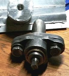
Here's mine that I made from an adjustable tool holder from Ebay. The cutting tool is a 1/4" lathe tool shaped to cut on the end and it makes 1/4" square holes. The front cap flange of the tool holder has been machined 1º off of perpendicular and installed shoved all the way to the outside of its adjustment range, and if a rod is inserted into the bronze bearing cup and the assembly rotated in a lathe chuck the rod appears to make an X shape in the air. The tool is cutoff so that its cutting edge is located as close as I can get it to the crossover of the X seen before.
When chucked in either the mill or the lathe, as the chuck rotates one angular position is a little closer to the work than all the rest so as that position comes to each corner it pushes the tool a little deeper into the work and by successively cutting each corner the square hole progresses into the work. At some point, determined by the relief ground into the tool, the tool shank begins contacting the entry hole and so it can progress no further into the work. That's why you see commercially made tools with long reliefs ground into them so that the tool can go deeper but it's also taking significant meat from the tool core making it weaker.
It takes a lot of force from the machine and a generous amount of lube is required but the broaching goes surprisingly fast at high spindle rpms. The operation leaves inward turned flower petal looking chips in the hole and those are easily broken out with a pointed tool later. I made a steel carrier for that tool which the cup bearing rotates around and if I want a different size hole then I have to make a carrier for that different sized tool, but so far making 1/4" square holes deep enough to get a ratchet into has been enough for me.


 LinkBack URL
 About LinkBacks


 Reply With Quote


Bookmarks