Free 186 More Best Homemade Tools eBook:  
Get 2,500+ tool plans, full site access, and more.

User Tag List

Page 5 of 5 FirstFirst 1 2 3 4 5
Results 41 to 49 of 49

Thread: Repair guy

  1. #41
    Supporting Member metric_taper's Avatar
    Join Date
    Mar 2017
    Location
    Marion, Iowa
    Posts
    628
    Thanks
    242
    Thanked 270 Times in 164 Posts

    metric_taper's Tools
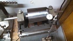
    I also got a short 4MT drill chuck arbor, and was able to mount the sleeve between centers of my newly acquired bench center on a sine plate (also newly found). As the assumed angle was a 1:20 taper, I put a .25" gauge block under the bar of this 10" center sine plate. 1:40 would be the tangent angle, which solving for sine was a 0.249919 gauge block, I figured .250 is close enough.
    Counting the clicks difference between the 2 ends of the taper sleeve, I found an error of 0.0057". This explains my 0.0045 runout of this sleeve installed in my lathe spindle.
    I had to make a tool for this setup (the gauge block spindle), as the gage block (purchased used recently with no spindle or snug) has a snug for 1/4", and my indicator snug wanted 10mm, so I cut off a piece of 10mm O2 drill rod (just happened to have that bastard size), and turned down 3/4" of the end to 1/4" diameter. Which I don't count as tool making for real. More cobbling for lack of tools.


    Repair guy-2017-03-24-sine-plate-bench-center-setup-lathe-sleeve-010.jpg

    Runout measurement was 0.01mm or about 0.0004".

    Next is to put this sleeve in my lathe, and be able to drive torque to either tool bit cut, or easier to tool post grind. But .005 grinding of material removal is several passes.

    I've looked on this site for a jig to hold the diamond point wheel dressing tool, and didn't find one. Anyone here seen a design that works for external and internal wheel dressing? What I have now is a piece of 1" round stock, cross drill for the diameter of the diamond point, near one end, and a set screw drill into the center end to hold this tight. I then chuck this in the 3 jaw and point the diamond point at the TPG wheel. It works, but there must be a better jig.

    186 More Best Homemade Tools eBook

  2. #42
    Supporting Member Moby Duck's Avatar
    Join Date
    Jan 2016
    Posts
    402
    Thanks
    1,274
    Thanked 206 Times in 131 Posts

    Moby Duck's Tools
    Quote Originally Posted by metric_taper View Post
    This adapter came with the lathe. As indicated in the thread, every incorrectly made part clearly was assembled by the Chinese manufacture and exported this special through Grizzly. I have thought of making a new sleeve, I still need to accurately measure the spindle taper just to get something close. I'm retired, and probably will never need anything to fit this spindle hole but a true running center. I can't live with the 5 thou of runout. I've had the lathe since 2004, and just now finding the issue. Most work is always held in 3 or 4 jaw 12 inch chucks.
    If you have had the lathe since 2004 and have never used the adaptor, and rarely turn anything between centres, and are unlikely to buy a set of collets for a lathe of this size, then I think that you are going to a lot of trouble for nothing.
    Just take an appropriate sized piece of round steel bar, hold it with a 3 jaw chuck and turn a centre point end on it using the compound. It doesn't need fancy grinding, or even hardening, and it will run exactly concentric with the spindle, and it will remain so until removed from the chuck. In another 12 years when you might need to use it again, simply remount in any chuck and skim and true the centre point.
    p.s. I am not a toolmaker but the above has always worked well for me. Precision is nice but not always necessary, and I certainly wouldn't expect to get it from a big cheap lathe.

    2,500+ Tool Plans

  3. #43
    Banned
    Supporting Member

    Join Date
    Feb 2014
    Posts
    69
    Thanks
    0
    Thanked 14 Times in 11 Posts
    Quote Originally Posted by Moby Duck View Post
    I am not a toolmaker but the above has always worked well for me. Precision is nice but not always necessary, and I certainly wouldn't expect to get it from a big cheap lathe.
    Excellent point as virtually all the between centers turning has used the described method. The jaws are also excellent points on which the lathe dog can sit. If you use a four jaw you can more easily produce 2 and 4 lead threads. With the 3 jaw 3 lead threads are possible.

  4. #44
    Supporting Member metric_taper's Avatar
    Join Date
    Mar 2017
    Location
    Marion, Iowa
    Posts
    628
    Thanks
    242
    Thanked 270 Times in 164 Posts

    metric_taper's Tools
    Quote Originally Posted by Moby Duck View Post
    If you have had the lathe since 2004 and have never used the adaptor, and rarely turn anything between centres, and are unlikely to buy a set of collets for a lathe of this size, then I think that you are going to a lot of trouble for nothing.
    Just take an appropriate sized piece of round steel bar, hold it with a 3 jaw chuck and turn a centre point end on it using the compound. It doesn't need fancy grinding, or even hardening, and it will run exactly concentric with the spindle, and it will remain so until removed from the chuck. In another 12 years when you might need to use it again, simply remount in any chuck and skim and true the centre point.
    p.s. I am not a toolmaker but the above has always worked well for me. Precision is nice but not always necessary, and I certainly wouldn't expect to get it from a big cheap lathe.
    I know the method your referring to of making a center held in the 3 jaw.
    I do have a project that needs to be between centers. The problem is this lathe is a short bed (I purchased on purpose for lack of floor space). It's only 40 inches between centers. The 12 inch lathe chuck consume more then 10 inches of this. I have a shaft project ~35".

    I did learn that the taper is a 90mm gauge line metric taper 1:20 ratio. And I learned the sleeve is where the error is. And I learned a whole bunch of new things I never knew before, like making measurements on a surface plate.

  5. #45
    Banned
    Supporting Member

    Join Date
    Feb 2014
    Posts
    69
    Thanks
    0
    Thanked 14 Times in 11 Posts
    Well that certainly changes things.

    I return to a previous post where I recommended using witness marks to align the center in the spindle at zero run out. Another option is to make witness marks then grind the center true to the axis of the lathe.

  6. #46
    Supporting Member metric_taper's Avatar
    Join Date
    Mar 2017
    Location
    Marion, Iowa
    Posts
    628
    Thanks
    242
    Thanked 270 Times in 164 Posts

    metric_taper's Tools
    Quote Originally Posted by Dr Stan View Post
    Well that certainly changes things.

    I return to a previous post where I recommended using witness marks to align the center in the spindle at zero run out. Another option is to make witness marks then grind the center true to the axis of the lathe.
    If this sleeve did not 'rock' in the opening, then regrinding the 4MT center would work. But I can lightly tap with a brass hammer to move it in the bore, and I can get a TIR of 4.5 thou. at the sleeve edge, the center runout is magnified as it stands out another 2 inches. The minor diameter hits first, so it seems tight, but it's not. What I learned with blueing was this acted as a grease, and the sleeve would never seat.

    It really looks like the sleeve is the bad part here. I can fix this sleeve.
    And in the process of getting to this point, I learned many new skills. And really that is what having a machine shop is about. Otherwise, I'd be in the class of not fixing things, and just buying new, or paying someone else to do it. And I think I would be a brain dead human, with no interest in how things work.

    The lathe can machine to tenths tolerances, it's worth fixing. It is what I could afford at the time, and it has served me well, even with seeing it's issues.

  7. #47
    Supporting Member metric_taper's Avatar
    Join Date
    Mar 2017
    Location
    Marion, Iowa
    Posts
    628
    Thanks
    242
    Thanked 270 Times in 164 Posts

    metric_taper's Tools
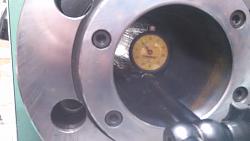
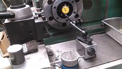
    I did not like the accuracy and repeatability of measuring the taper angle of the lathe headstock. Also the snug was in the view of the dial. After reading a few reviews of indicator holders. I sprung for a Noga. It makes every other holder now junk in the shop. This thing is rigid. I have 2 different size knockoffs of this, and they are too compliant just from the indicator spring forces. As well the magnetic block is so poorly made they rock on a flat surface. The Noga with zero adjust at the base just made the setup quick and non irritating.

    Repair guy-2017-03-29-noga-indicator-holder-014.jpgRepair guy-2017-03-29-noga-indicator-holder-002.jpg
    The lathe has a DRO on the carriage and cross, so I was able to reference the indicator location, with it's taper measurement.
    As I believe the head stock taper is a 90mm gauge line, metric taper of 20:1, I found that at 40 mm, the indicator shown 1.008mm, and at 80mm, 2.020mm (which are half angle measurements). The indicator is .01mm resolution, but my eye can interpolate a bit better. So the headstock taper is off by just a tiny bit, as it should be 1.000mm per 40mm travel. I probably will leave that be.

  8. #48

    Join Date
    Nov 2016
    Posts
    6
    Thanks
    16
    Thanked 0 Times in 0 Posts
    If you are bottoming out the taper cannot seat as intended. since the adapter is not doing you any good anyway , try taking a small amount off the bottom end with a grinder, all the way around , and see if this does not let it seat out.

  9. #49
    Supporting Member metric_taper's Avatar
    Join Date
    Mar 2017
    Location
    Marion, Iowa
    Posts
    628
    Thanks
    242
    Thanked 270 Times in 164 Posts

    metric_taper's Tools
    Quote Originally Posted by Ron 2 View Post
    If you are bottoming out the taper cannot seat as intended. since the adapter is not doing you any good anyway , try taking a small amount off the bottom end with a grinder, all the way around , and see if this does not let it seat out.
    I was able to make the measurement of the lathe spindle taper, and this sleeve. The sleeve has a consistent taper angle, it needs to have this angle corrected for the lathe. The lathe taper is off by 0.01mm/40mm (it should be 1.000mm per 40.000mm). But I need to verify that using a different dial indicator, as the one I used may have error.
    For sure, I need to fix the sleeve to match the lathe taper, as it sits with 4 inches of mating surface. Too many other projects in the que (hanging drywall, so I can hire a finisher on a 10 year old project, and I'm not getting younger).


    2,500+ Tool Plans

Thread Information

Users Browsing this Thread

There are currently 1 users browsing this thread. (0 members and 1 guests)

Bookmarks

Posting Permissions

  • You may not post new threads
  • You may not post replies
  • You may not post attachments
  • You may not edit your posts
  •