Free 186 More Best Homemade Tools eBook:  
Get tool plans

User Tag List

Page 1 of 5 1 2 3 4 5 LastLast
Results 1 to 10 of 49

Thread: Repair guy

  1. #1
    Supporting Member metric_taper's Avatar
    Join Date
    Mar 2017
    Location
    Marion, Iowa
    Posts
    612
    Thanks
    238
    Thanked 266 Times in 161 Posts

    metric_taper's Tools

    Repair headstock spindle morse taper sleeve adapter

    Current project is to fix a Grizzly G3621 (16X40) headstock spindle taper. All the documentation says it is a #6 Morse taper, but with a 80mm (3.125) through hole, it's bigger then 6MT (it is also bigger then 7MT). So I now believe it is a 90mm gage line, metric taper 1:20 ratio (would like to know where tooling for this can be found, but $ for custom, drives me to make my own). The sleeve that came with the lathe that adapts a 4MT center to this spindle taper, is sloppy where the taper bottoms out, and leaves the end protruding from the spindle with .0045 runout. I can rock it back and forth with a brass hammer, but this is unacceptable.
    So I need to see if the sleeve is wrong, or the spindle.
    I'm looking for tooling ideas to both measure this, and do the correct repair. I assume the sleeve and spindle are hardened.
    I ran into this sight from the plans for a "Zero it" indicator holder. I purchased one from Shars, which is absolute junk, as there is .9mm of slop in the sliding zero set parallel rods to holder hole size. No way this can hold any tolerance to center or tram the spindle.

    186 More Best Homemade Tools eBook
    Last edited by metric_taper; Mar 29, 2017 at 01:57 PM. Reason: moved intro to profile, fix title (3-29-17)

  2. #2
    Jon
    Jon is online now Jon has agreed the Seller's Terms of Service
    Administrator
    Supporting Member
    Jon's Avatar
    Join Date
    Jan 2012
    Location
    Colorado, USA
    Posts
    26,438
    Thanks
    8,100
    Thanked 40,247 Times in 11,775 Posts
    Hi metric_taper - welcome to HomemadeTools.net

    I'm going to move this discussion into our Tools in Progress subforum so that everyone can take a look.

    2,000+ Tool Plans

  3. #3
    Supporting Member metric_taper's Avatar
    Join Date
    Mar 2017
    Location
    Marion, Iowa
    Posts
    612
    Thanks
    238
    Thanked 266 Times in 161 Posts

    metric_taper's Tools

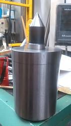
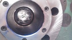
    Photos of lathe spindle hole and center adapter sleeve

    The lathe does have a taper attachment, but it needs some gib and other adjustments to work smoothly.

    The existing sleeve that adapts the 4MT center to the lathe spindle
    Repair guy-2017-02-16-lathe-test-bar-029.jpg
    This spindle is a D1-8 chuck mount.
    Repair guy-2017-02-22-morse-taper-blueing-lathe-photos-011.jpg
    I over applied the Dykem Hi-spot, but the sleeve was only contacting at the bottom of the taper.
    Repair guy-2017-02-22-morse-taper-blueing-lathe-photos-019.jpg
    The sleeve. I did over apply the hi-spot, to where it acted like a grease and prevented the taper from locking.
    Repair guy-2017-02-22-morse-taper-blueing-lathe-photos-042.jpg

  4. The Following User Says Thank You to metric_taper For This Useful Post:

    olderdan (Mar 18, 2017)

  5. #4
    Supporting Member
    Join Date
    Sep 2015
    Location
    Kansas
    Posts
    75
    Thanks
    0
    Thanked 47 Times in 29 Posts
    That may be a 7 Morse taper. You can look up the specs in Machinery's Handbook. If you find the spindle is worn or not at the correct angle, you can recut it with a carbide insert boring bar. You can use the taper attachment, or swing the compound slide around to the correct angle. I like to use the compound for short angles.

    Once you determine what the taper should be (the model G0749 is a #7MT) You can easily set the compound slide to the desired taper like this:
    1- Put a bar in the chuck or collet and turn to get a full cleanup on the material diameter with a good finish. Diameter must be the same for the length of the turned part. Keep part in place until angle is set.
    2- Calculate a right triangle for one side of the taper. Set up a dial indicator perpendicular to the turned part, on the side facing the operator. The compound slide is the hypotenuse, indicator stem is the short side and the part is the long side.
    3- Adjust the angle of the compound until the dial indicator reads the number of the short side when the compound is dialed the length of the long side. Tighten compound slide in place.
    4- Remove indicator and bar, add part to be turned and cutting tool, and cut taper. In this case, the part to be turned would be the spindle taper. No need for a toolpost grinder, just go over the surface several times with the carbide insert. Make sure the toolpost is tight, so it doesn't move during the cutting process.
    Last edited by Toolguy; Mar 17, 2017 at 02:30 PM.

  6. #5
    ChrisB257's Avatar
    Join Date
    Dec 2016
    Posts
    21
    Thanks
    15
    Thanked 16 Times in 7 Posts

    ChrisB257's Tools
    I hope I am reading the problem right.
    My initial thought is, to clock the internal taper of the spindle to work out exactly what the taper is - decimal or inch - i.e, x fractional inch taper per y inch linear - or metric equivalent. Then, see if there is some way to set up the adapter by some means - mandrel of some sort and get it running true via a 4-jaw chuck... this is the awkward bit! Not sure yet quite what I'd do without the adapter actually in hand!
    If that can work then the adapter can be clocked to see what the taper discrepancy is exactly, then set up for the correct taper and grind externally or even cut with a carbide insert even if hardened. Now, if this could improve things the next step could be to lap the adapter and spindle gradually together until the fit is correct - which would mean then having to always use that spindle taper/adapter combination for good. A good 1/10s indicator would be useful.
    One other thought - if internal taper of spindle could be measured well enough - use that info to turn a new dummy adapter out of ordinary CRS and try and get that right for fit. If that worked then drill and ream for end to take a Morse dead center. It could serve even if not hardened.
    Sorry long winded but sort of thinking aloud right now
    Ain't technology great - until it goes wrong!
    The Old Man's Shop

  7. The Following User Says Thank You to ChrisB257 For This Useful Post:

    metric_taper (Mar 19, 2017)

  8. #6
    Supporting Member Gary A. Wills's Avatar
    Join Date
    May 2015
    Posts
    25
    Thanks
    15
    Thanked 14 Times in 9 Posts
    Do you have any runout when using the chucks? I'd mount the sleeve on an arbor mount a center and center it in a four jaw chuck and using a dog to drive I'd set up a grinding fixture on the tool post . Indicate the compound to the taper and then using a seperate indicator on the bottom of the compound. Then I'd take a test grind full length of the taper. If it cleans up all the blue dye I'd loosen and tap the compound about .002 at the tailstock end. Recut the grind measure the large end if it matches the taper in the head I'd stop and recheck the fit in the spindle. Easy to save your zero by just taking the arbor and part out from the centers. Remove the chuck and Ck the fit with blue dye. It may take awhile but you can fit it a few thousandth at a time. If the spindles out you'll need to recut the bore. Hopefully it's just the sleeve.
    Last edited by Gary A. Wills; Mar 17, 2017 at 02:01 PM.

  9. #7

    Join Date
    Sep 2014
    Location
    Danville, IN
    Posts
    4
    Thanks
    0
    Thanked 0 Times in 0 Posts
    Not positive what your objective is. Are you trying to fix the head stock spindle taper or identify what it is? First off is there something wrong with the spindle? Does it have a problem from an accident? If the spindle in the lathe runs true the first thing is to identify the taper. Surely it is a standard unless someone has modified it. If you are trying to put it back to a standard taper you should find someone with a DuMore tool post grinder with accessory long axis slide of its own. They do exist and are used for truing precision machines after bearing changes. Been there done it! But the spindle taper should be where to start and go from there.

  10. #8
    Supporting Member Gary A. Wills's Avatar
    Join Date
    May 2015
    Posts
    25
    Thanks
    15
    Thanked 14 Times in 9 Posts
    Do you have any runout when using the chucks? I'd mount the sleeve on an arbor mount a center and center it in a four jaw chuck and using a dog to drive I'd set up a grinding fixture on the tool post . Indicate the compound to the taper and then using a seperate indicator on the bottom of the compound. Then I'd take a test grind full length of the taper. If it cleans up all the blue dye I'd loosen and tap the compound about .002 at the tailstock end. Recut the grind measure the large end if it matches the taper in the head I'd stop and recheck the fit in the spindle. Easy to save your zero by just taking the arbor and part out from the centers. Remove the chuck and Ck the fit with blue dye. It may take awhile but you can fit it a few thousandth at a time. If the spindles out you'll need to trout the bore. Hopefully it's just the sleeve.

  11. #9
    Banned
    Supporting Member

    Join Date
    Feb 2014
    Posts
    69
    Thanks
    0
    Thanked 14 Times in 11 Posts
    Morse tapers are approx 5/8" per foot, but if you look them up in Machinery's you'll soon discover they vary a little by taper size. I would determine exactly which taper you have then build a bronze lap with the appropriate taper. Charge it with diamond dressing compound and lap the spindle. I recommend this as you want to clean up the spindle and remove as little metal as possible. BTW if you use the compound remember you'll be traveling on the hypotenuse instead of parallel to the axis when setting up the taper. It should be measured/set parallel to the axis.

    I realize a piece of bronze that size is going to be expensive, but there is a work around. Make a steel lap around .050" on the diameter smaller than the finish size then build it up with brazing rod. If you have access to a spray metal unit that would be just about perfect.

  12. #10

    Join Date
    Mar 2016
    Posts
    11
    Thanks
    0
    Thanked 9 Times in 5 Posts

    firewizerp's Tools
    Unless your will to spend $ on a set of quality dials it is nearly impossible to get a true reading. I have found that with a mag mount tool holder and a simple contractor's line laser l and a sheet of graph paperyou can get readings equal to or better than any set of dials.
    Simply graph outline of your part place outline directly under, set up the line laser so that the beam is just blocked by part, the slowly rotate marking on paper and part each time lasers visible on paper. Sounds complicated on paper but is rather easy to set up and read/measure
    For internal taper I've used "alumilite"and " quick cast" casting compounds to make +castings center a rod into the taper bore pour casting compound. Make sure and use a good releasing agent, and before removal of the cast make indexing marks on cast and adapter. And measure same way.Done correctly youll have an accurate wear pattern and or out of round measurements. From there you can decide the proper solution. I hope this makes some sense, not good at describing things better at hands on.

Thread Information

Users Browsing this Thread

There are currently 1 users browsing this thread. (0 members and 1 guests)

Bookmarks

Posting Permissions

  • You may not post new threads
  • You may not post replies
  • You may not post attachments
  • You may not edit your posts
  •