Free 186 More Best Homemade Tools eBook:  
Get 2,500+ tool plans, full site access, and more.

User Tag List

Results 1 to 4 of 4

Thread: Power Steering Hose Fitting

  1. #1
    Supporting Member gatz's Avatar
    Join Date
    Feb 2016
    Posts
    180
    Thanks
    2
    Thanked 154 Times in 54 Posts

    gatz's Tools

    Power Steering Hose Fitting

    I was searching for a shop or business that could furnish and crimp a ferrule onto a hose assembly. The assembly is going to be used for a Jaguar IFS that I've installed on a 40 Chrysler Coupe.

    Hose a'y,
    Power Steering Hose Fitting-ps-pressure-line-pump-banjo-jag-steering-box.jpg

    Countless inquiries were made to places like NAPA, AutoZone, Dakota Fluid Power, and various other hydraulic shops; local and elsewhere.
    No-one seemed to be able to do the job or just didn't want to.

    So....I took it upon myself to make the req'd ferrule and crimper.
    The ferrule was made from A513 steel as this seemed to be the best for avoiding any cracking when crimped.
    A 1/2" schedule 160 pipe nipple was chosen.
    A piece was cut to 0.94 and the ID was bored to 0.75 x 0.88 dp; however, the OD was not turned.
    The open end was flared slightly using a 7/8" steel ball.
    Power Steering Hose Fitting-hose-crimp_2.jpg

    The 6-sided crimper. Making this took some time...haha.
    But, I had made something similar back in the 70's for a company that made farm sprayers.
    Power Steering Hose Fitting-crimper.jpg

    Hose and ferrule before crimp, top view
    Power Steering Hose Fitting-hose-crimper_1.jpg

    ...bottom view
    Power Steering Hose Fitting-hose-crimper_2.jpg

    Crimped assembly
    Power Steering Hose Fitting-crimped-hose_1.jpg


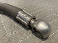
    close-up view
    Power Steering Hose Fitting-crimped-hose_2.jpg

    The reason it looks rough is because, as mentioned above, no turning was done to the OD
    I think it will hold the 1500 psi.

    186 More Best Homemade Tools eBook

  2. The Following 4 Users Say Thank You to gatz For This Useful Post:

    DIYer (Oct 13, 2024), ductape (Oct 12, 2024), IntheGroove (Oct 12, 2024)

  3. #2
    Content Editor
    Supporting Member
    DIYer's Avatar
    Join Date
    Aug 2013
    Posts
    3,055
    Thanks
    798
    Thanked 1,897 Times in 1,692 Posts


    Thanks gatz! We've added your Power Steering Hose Fitting to our Steering category,
    as well as to your builder page: gatz's Homemade Tools. Your receipt:


    2,500+ Tool Plans
    New plans added on 01/15/2025: Click here for 2,702 plans for homemade tools.

  4. #3
    Supporting Member
    Join Date
    Feb 2015
    Location
    Prescott, AZ
    Posts
    60
    Thanks
    1
    Thanked 101 Times in 26 Posts

    Shelly142's Tools
    gatz, nicely done.
    Have experienced a similar problem years ago with an engine swap. I don’t remember having great difficulty in finding someone to build a unique hose for my application, but it did take some investigation. This is a very clever tool you came up with to solve your particular issue. Is it possible that you developed
    drawings or sketches for this tool that you could share?
    Shelly

  5. #4
    Supporting Member gatz's Avatar
    Join Date
    Feb 2016
    Posts
    180
    Thanks
    2
    Thanked 154 Times in 54 Posts

    gatz's Tools
    Thanks, @Shelly142
    Hope this isn't too boring…. the “design” as it were, was mostly just guess-work. I knew the dim of the hose over the fitting to be just over 3/4” and adding about a 0.05 wall, worked from there.
    Fgured approx 0.88 nominal “jaws” + 0.01 & 3/8” per side for the jaws which came to about 1.65 diameter.
    I had a chunk of 3 1/4” dia S.S. and machined it to 3/4” thick. Bored the ID to the 1.65 dia. Milled 6 flats to obtain 3” width. Tapped 3/8-16 holes through the flats at centerline
    In addition, 6) 1/4-20 holes were tapped for the jaw retaining collars. To make the jaws, I turned another piece of steel 7/8” thick to 0.75 ID, 3” OD, and turned a step diameter to fit the 1.65; leaving a 1/8 flange. A hole pattern was drilled to allow fixturing to a block of alum, this round piece was then saw-cut into 6 pieces, then milled sides parallel to 0.75 wide using the previously drilled holes & mounted to the alum piece. A few additional cuts were made at 45deg on each jaw so that the material of the ferrule could bulge outward into the “void” The amount was mostly guessed at, but when done, seemed to be about right.
    A 5/16 blind guide hole was drilled into the surface that was the 1.65 diameter. The ends of 6) 3/8-16 gr8 bolts wre turned down to 5/16 dia to fit the blind holes.
    a suitable mount was made to hold the assembly.
    Tightening the bolts in sequence crimped the ferrule nicely.
    So, I did have many sketches, but many changes were made as it prgressed.
    One certainty…. I'd not use S.S. again…much too difficult to tap, even using bigger than std tap-drill sizes.

    Many, many years ago, I built a hose crimper for a company I had worked for. It used 4 dies actuated by toggles inside a large ring. This was used on ag sprayers.
    It saved them a lot of assembly time as they could pass completed crimped fittings through the crimper, whereas before they had to crimp the hoses onto the barb fittings and screw them together to make up the needed lengths. There had always been a lot of fussin' around getting the drops oriented. This new crimper solved those problems.

    OR….. one could buy this

    https://www.amazon.com/dp/B0DC6M1FFP...WxfdGhlbWF0aWM


    2,500+ Tool Plans

Thread Information

Users Browsing this Thread

There are currently 1 users browsing this thread. (0 members and 1 guests)

Bookmarks

Posting Permissions

  • You may not post new threads
  • You may not post replies
  • You may not post attachments
  • You may not edit your posts
  •