Free 186 More Best Homemade Tools eBook:  
Get 2,500+ tool plans, full site access, and more.

User Tag List

Page 1 of 2 1 2 LastLast
Results 1 to 10 of 12

Thread: Pneumatic Power Drawbar for Bridgeport Mill

  1. #1
    Supporting Member thehomeengineer's Avatar
    Join Date
    Nov 2017
    Location
    Berkshire UK
    Posts
    742
    Thanks
    751
    Thanked 2,204 Times in 431 Posts

    thehomeengineer's Tools

    UPDATED Pneumatic Power Drawbar for Bridgeport Mill UPDATED

    After falling ill, I was struggling to change the tooling on my Bridgeport mill so decided to build a pneumatic power draw-bar. There are plenty of great videos on You Tube and other sites for research, So I decided to try and incorporate all the bits I liked in to this project. This works very well and makes tool changing a lot simpler. Some of the hardware was purchased from eBay air fittings, air hose, cylinder linear bearings and shafts, springs, approximate cost for items £50.00 the rest was manufactured in the workshop.


    UPDATE
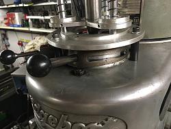
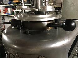
    After using power-draw for a few years it occasionally would play up and lift the back-gear lever and jam. I removed it this weekend as I had just had enough with the jamming issue. (doesn't help when you are not well and patients are a bit short) However after 20 minutes of having to manually change the tooling it was definitely the next urgent job to sort and sooner than later. So I have now fixed the power-draw bar directly to the top aluminium casting via three steel stand offs and an aluminium plate machined to suit. This still allows the back-gear and brake lever to operate without any interference from the modification.

    Anyone considering building a power draw-bar please don't make the same mistake I made and bolt direct to top casting and not the back-gear castings. As per 1st photo.

    The pillars/stand offs are 36mm high and 120 degrees apart on a 136mm Pitch circle diameter (PCD). The first pillar (datum point) is placed equally (by eye ) between the brake and back-gear lever. This allows the other pillars to miss nuts etc on the casting top. I used M6 threaded studding, screwed and loctited into the pillars to fit the aluminium top casting and M6 cap screws, plain washer and spring washer to lock the aluminium flange to pillars.
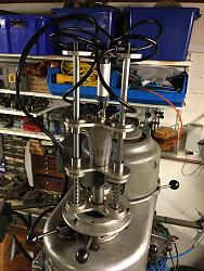
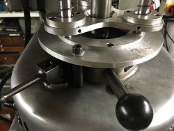
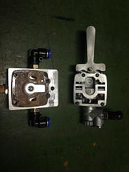
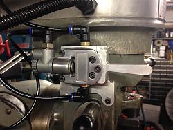
    Pneumatic Power Drawbar for Bridgeport Mill-img_3901.jpg Pneumatic Power Drawbar for Bridgeport Mill-img_3898.jpg Pneumatic Power Drawbar for Bridgeport Mill-img_3899.jpg Pneumatic Power Drawbar for Bridgeport Mill-img_3900.jpg

    Good luck in your power draw-bar build. One of the best modification I have ever-made. So much easier for tool changing and so quick.
    The Home Engineer

    186 More Best Homemade Tools eBook
    Last edited by thehomeengineer; Nov 7, 2019 at 01:59 PM. Reason: update improvements to power draw-bar

  2. The Following 7 Users Say Thank You to thehomeengineer For This Useful Post:

    extropic (Dec 15, 2017), HUMARIA (Sep 21, 2018), Jon (Dec 15, 2017), LMMasterMariner (May 18, 2018), Paul Jones (Dec 17, 2017), rossbotics (Dec 18, 2017), Seedtick (Dec 14, 2017)

  3. #2
    Banned
    Join Date
    Jul 2016
    Posts
    23
    Thanks
    18
    Thanked 1 Time in 1 Post
    Is the driver an air impact or an air ratchet?

    Do you have a pneumatic schematic to share?

    I'm guessing that the cylinder engages the socket with the drawbar and the springs disengage them.

    Are both the driver and the cylinder controlled by the same switch? I'm wondering about the timing of powering the driver before engaging the socket onto the drawbar (or is it a non-problem)? Or, are there separate switches for cylinder and driver?

    Real nice looking setup.

    2,500+ Tool Plans

  4. #3
    Supporting Member thehomeengineer's Avatar
    Join Date
    Nov 2017
    Location
    Berkshire UK
    Posts
    742
    Thanks
    751
    Thanked 2,204 Times in 431 Posts

    thehomeengineer's Tools
    Hi
    it is a butterfly impact driver and both the cylinder and driver are driven from one switch (The exsisting butterfly switch was removed from the top and modified).

    Pneumatic Power Drawbar for Bridgeport Mill-img_0708.jpg Pneumatic Power Drawbar for Bridgeport Mill-img_0734.jpg Pneumatic Power Drawbar for Bridgeport Mill-img_0710.jpg

    There is no timing the impact driver socket engages over the drawbar with no problems. I will have to draw out the the pneumatic set up and post, but for futher photos are on my web page. http://www.modelengineeringworkshop....er-drawbar.php
    Last edited by thehomeengineer; Dec 15, 2017 at 12:58 PM. Reason: photo correction

  5. The Following 4 Users Say Thank You to thehomeengineer For This Useful Post:

    extropic (Dec 15, 2017), LMMasterMariner (May 18, 2018), mwmkravchenko (Oct 19, 2019), Paul Jones (Dec 17, 2017)

  6. #4
    Banned
    Join Date
    Jul 2016
    Posts
    23
    Thanks
    18
    Thanked 1 Time in 1 Post
    Thank you again. I understand the controls now.

    In the pics, on your web site, I see a generous chamfer that you added to the top of the drawbar hex which may facilitate the socket engagement while the driver starting.

    Your work is a pleasure to see. Keep posting and you'll fit right in with the best I've seen on this site.

    PS: looking at the pics regarding "Bridgeport Mill VFD and Tachometer" I see some interesting clamps being used on the drill press. I don't think I've seen that type before. Are they another creation of yours?

  7. The Following User Says Thank You to extropic For This Useful Post:

    Paul Jones (Dec 17, 2017)

  8. #5
    Content Editor
    Supporting Member
    DIYer's Avatar
    Join Date
    Aug 2013
    Posts
    3,055
    Thanks
    796
    Thanked 1,895 Times in 1,690 Posts


    Thanks thehomeengineer! We've added your Pneumatic Drawbar to our Machining category,
    as well as to your builder page: thehomeengineer's Homemade Tools. Your receipt:


    New plans added on 01/06/2025: Click here for 2,686 plans for homemade tools.

  9. #6
    Supporting Member thehomeengineer's Avatar
    Join Date
    Nov 2017
    Location
    Berkshire UK
    Posts
    742
    Thanks
    751
    Thanked 2,204 Times in 431 Posts

    thehomeengineer's Tools
    Hi extropic
    Thank for the kind words and sorry for the delay in responding
    I made the clamps and now have about 10 sets of them if not more. I made my first one when I did my apprenticeship project some 34 years ago. The are very quick and useful to use, so decided to make a batch of them for the workshop. I will do another post on homemadetools.net for the clamps, as you are not the first person to ask about them.
    Thank you again for viewing my posts
    The home engineer

  10. #7
    Supporting Member Saltfever's Avatar
    Join Date
    Apr 2012
    Location
    NorCal
    Posts
    412
    Thanks
    406
    Thanked 146 Times in 104 Posts

    Saltfever's Tools
    Sorry I am late to this party by about 4 months. I couldn't see the clamps clearly in your link mentioned above. Did you subsequently post a clamp-specific thread yet?

  11. #8
    Supporting Member thehomeengineer's Avatar
    Join Date
    Nov 2017
    Location
    Berkshire UK
    Posts
    742
    Thanks
    751
    Thanked 2,204 Times in 431 Posts

    thehomeengineer's Tools
    Quote Originally Posted by Saltfever View Post
    Sorry I am late to this party by about 4 months. I couldn't see the clamps clearly in your link mentioned above. Did you subsequently post a clamp-specific thread yet?
    Thank you for your interest here is the link http://www.homemadetools.net/forum/c...p-system-65679
    The Home Engineer

  12. The Following User Says Thank You to thehomeengineer For This Useful Post:

    Paul Jones (May 18, 2018)

  13. #9
    Supporting Member Saltfever's Avatar
    Join Date
    Apr 2012
    Location
    NorCal
    Posts
    412
    Thanks
    406
    Thanked 146 Times in 104 Posts

    Saltfever's Tools
    Very Nice. THANK YOU. :-)

  14. #10
    Supporting Member thehomeengineer's Avatar
    Join Date
    Nov 2017
    Location
    Berkshire UK
    Posts
    742
    Thanks
    751
    Thanked 2,204 Times in 431 Posts

    thehomeengineer's Tools
    Hi All
    I have updated this old post today after modifying the way the power draw-bar attaches to the machine. So if building a power-draw bar don't make the same mistake I made.
    The Home Engineer

  15. The Following User Says Thank You to thehomeengineer For This Useful Post:

    Jon (Nov 7, 2019)

Thread Information

Users Browsing this Thread

There are currently 1 users browsing this thread. (0 members and 1 guests)

Bookmarks

Posting Permissions

  • You may not post new threads
  • You may not post replies
  • You may not post attachments
  • You may not edit your posts
  •