Free 186 More Best Homemade Tools eBook:  
Get 2,500+ tool plans, full site access, and more.

User Tag List

Results 1 to 7 of 7

Thread: Please help to wire up motor

  1. #1
    Supporting Member garage nut's Avatar
    Join Date
    Jul 2017
    Location
    Port Elizabet, SA
    Posts
    246
    Thanks
    92
    Thanked 443 Times in 109 Posts

    garage nut's Tools

    Please help to wire up motor

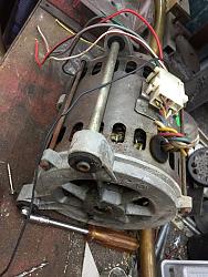
    Friend scrapped a Defy Auto Front loader washing machine, some 30 years old.

    Motor and Cap came my way, but no idea how to wire it.

    Please help to wire up motor-img_6549.jpg

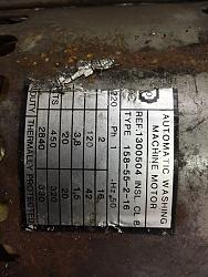
    It is a 240V AC single phase motor, 2 speed and the slow speed has forward and reverse.

    Please help to wire up motor-img_6546.jpg

    From the wiring I received the White wire seems to be Neutral as it has several spade connectors attached so assume it went to all the switched and elements and thing.

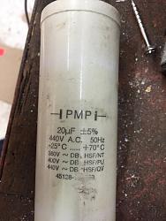
    This is the cap that came with it.

    Please help to wire up motor-img_6550.jpg

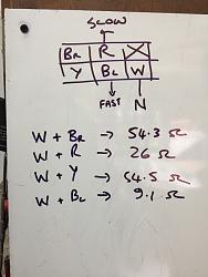
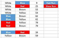
    By doing the internet search I found out the Run winding has the lower resistance and the start winding the higher resistance.

    This seem to work as I found the fast speed (9 Ohm) and the slow speed (26 Ohm) but do not start by itself and then if I connect the cap over any one of the high resistance coils it starts but causes a fairly loud hum.

    Please help to wire up motor-img_6552.jpg

    Please I need help as this motor will really be helpful with that rather low 450RPM. Any more info of pics will be no problem.

    186 More Best Homemade Tools eBook

  2. #2
    Supporting Member kess's Avatar
    Join Date
    Dec 2015
    Location
    Thessaloniki Greece
    Posts
    161
    Thanks
    83
    Thanked 317 Times in 82 Posts

    kess's Tools
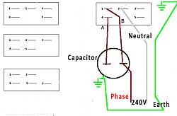
    Please help to wire up motor-555.jpg

    Connector can be vary according the brand
    but the same numpers represent the same wires/connections

    Quick speed
    Capacitor → 1, 4
    Phase → 1
    Neutral → 2
    Not connected 3, 5
    *******************
    Slow speed 1
    Capacitor → 3, 5
    Phase → 3
    Neutral → 2
    Not connected 1, 4
    ********************
    Slow speed 2 (In reverse direction of Slow speed 1)
    Capacitor → 3, 5
    Phase → 5
    Neutral → 2
    Not connected 1, 4

    2,500+ Tool Plans
    Last edited by kess; Dec 20, 2018 at 01:47 PM.

  3. The Following User Says Thank You to kess For This Useful Post:

    garage nut (Dec 20, 2018)

  4. #3
    Supporting Member garage nut's Avatar
    Join Date
    Jul 2017
    Location
    Port Elizabet, SA
    Posts
    246
    Thanks
    92
    Thanked 443 Times in 109 Posts

    garage nut's Tools
    so for my understanding....

    I must use the sketch to determine what number configuration my motor is using.

    So because I have no wire connected to the top Rh terminal my plug configuration should be the 3rd schematic
    [1, 2, Nothing]
    [5, 4, 3 ]

    From the wiring received with the motor terminal 3 appears to be the Neutral.
    any way to check what wire is neutral?

    Thanks Again.

    Last edited by garage nut; Dec 20, 2018 at 08:01 PM.

  5. #4
    Supporting Member garage nut's Avatar
    Join Date
    Jul 2017
    Location
    Port Elizabet, SA
    Posts
    246
    Thanks
    92
    Thanked 443 Times in 109 Posts

    garage nut's Tools
    Not working on this motor.

    Perhaps if somebody can explain to me the science behind an AC induction motor.

    This is what I learnt from the net....

    There are RUN windings ( Low resistance) and START windings (High resistance).
    Centrifugal switch somewhere inside to switch off start windings....sometimes.

    So seamed easily enough to measure all the coils and as I know it is a 2 speed motor, the lowest 2 readings will be the 2 RUN windings.

    Please help to wire up motor-resistance.jpg

    Then find the common wire connected to both these coils and it should be your Neutral. Turned out to be the White wire.

    Anything wrong with my logic so far?

    Now to find the Start coil....should be one of the coils also connected to the White wire. So Brown or Yellow.

    Tried both and it still only hums.

    Connecting Neutral to White and Live to Red or Blue runs perfectly if you give the motor a spin in one or the other direction.

  6. #5
    Supporting Member garage nut's Avatar
    Join Date
    Jul 2017
    Location
    Port Elizabet, SA
    Posts
    246
    Thanks
    92
    Thanked 443 Times in 109 Posts

    garage nut's Tools
    Found some info that a faulty Capacitor can also be the cause.

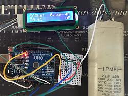
    My multi meter can not test a cap so quickly threw this together with an Arduino micro controller.

    Please help to wire up motor-cap-tester.jpg

    Cap spec is 20 MicroF and tester confirms it so Cap seems to be GOOD.


    Credit to ElectroNoobs
    Last edited by garage nut; Dec 22, 2018 at 07:40 AM.

  7. #6
    Supporting Member kess's Avatar
    Join Date
    Dec 2015
    Location
    Thessaloniki Greece
    Posts
    161
    Thanks
    83
    Thanked 317 Times in 82 Posts

    kess's Tools
    Method 1
    black - red: 28Ω auxiliary coil of fast speed
    black - yellow: 65Ω
    black - green: 65Ω
    black - blue: 12Ω cardinal coil of fast speed
    red - yellow: 92Ω
    red - green: 91Ω
    red - blue: 40Ω
    yellow - green: 74Ω
    yellow - blue: 76Ω
    green - blue: 76Ω
    black cable = common
    red cable = auxiliary fast
    blue cable = cardinal fast

    Since search winding goes from one to the common and the other on another cable, it goes without saying that the smallest measurements will definitely contain the common cable, since the larger ones will certainly be serial winding measurements.
    The pair of cables with the smaller resistance is the cardinal coil of fast speed.
    The pair with the next highest resistance at the range is the auxiliary coil of fast speed.
    As a result, the two remaining cables will be slow turns. Attention, here are not just two windings, one main and one auxiliary.
    Since at slow speed the motor is made to move in both directions, we expect to have symmetry in the measurements. That is, between black - green and black - yellow = same resistance of 65Ω.
    So why do not we just have two windings there? Because if we had, we would expect to see between yellow and green 65Ω + 65Ω = 130Ω. But we only have 74Ω.
    So there is another winding where it throws the resistance.
    As verification, we can say the following:
    1. The measurement between red and green will be as much as the measurement between red - black and black - green, ie 28Ω + 65Ω = 93Ω. Indeed the measurement gave 91Ω very close.
    2. The measurement between red and yellow will be as much as the measurement between red - black and black - yellow, ie 28Ω + 65Ω = 93Ω. Indeed the measurement gave 92Ω very close.
    3. The measurement between blue - green will be as much as the measurement between blue - black and black - green, ie 12Ω + 65Ω = 77Ω. Indeed the measurement gave 76Ω very close.
    4. The measurement between blue - yellow will be as much as the measurement between blue - black and black - yellow, ie 12Ω + 65Ω = 77Ω. Indeed the measurement gave 76Ω very close.
    Method 2
    Pair 1, 4 65,4Ω
    Pair 1, 2 22,4Ω
    Pair 1, 3 76,2Ω
    Pair 1, 5 76,2Ω
    Pair 3, 5 108,2Ω
    Pair 3, 4 97,4Ω
    Pair 3, 2 54,4Ω
    Pair 4, 5 97,4Ω
    Pair 2, 5 54,4Ω
    Pair 2, 4 43,6Ω
    It is first to find out who is the common. We see from the above what or most preferred which contact has the least Ohm. And we find for the above case that these are the below couples with the lower Ohm.
    1 - 2 22,4Ω
    3 - 2 54,4Ω
    2 - 5 54,4Ω
    2 - 4 43,6Ω
    Therefore, the above couples show the "2" majority. So this contact will be used for (common).
    Right/left of (common) is split between slow/fast pairs. And if we observe "visually" and "fast" which of the contacts 1 - 4 and 3 - 5 (pairs) have the next largest ones in Ohm (except the common cable) we will see that
    1 - 4 fit for fast turns (1-4 65.4Ω)
    3 - 5 fit for slow turns (3-5 108,2Ω)
    Hope this to help you.

  8. The Following User Says Thank You to kess For This Useful Post:

    garage nut (Dec 22, 2018)

  9. #7
    Content Editor
    Supporting Member
    DIYer's Avatar
    Join Date
    Aug 2013
    Posts
    3,055
    Thanks
    798
    Thanked 1,896 Times in 1,691 Posts


    Thanks garage nut! We've added your Capacitor Tester to our Electrical category,
    as well as to your builder page: garage nut's Homemade Tools. Your receipt:


    2,500+ Tool Plans
    New plans added on 01/13/2025: Click here for 2,698 plans for homemade tools.

Thread Information

Users Browsing this Thread

There are currently 1 users browsing this thread. (0 members and 1 guests)

Bookmarks

Posting Permissions

  • You may not post new threads
  • You may not post replies
  • You may not post attachments
  • You may not edit your posts
  •