Hi guys
I started working through a shortlist of jobs and modifications focused on and around my old Grayson lathe last Sunday.
She's had a couple of minor niggles and problems in need of attendance for a while now, one of them being the motor which is rather old and nearing the end of it's life and was noticeably struggling, even in backgear.
Once I had a bit of cash saved up for a replacement, I did some shopping around for one with the same specs as the old one (1/4hp single phase 1450rpm). However, as I work at a factory that makes variable frequency drives, I ended up getting a new/old stock 2hp three phase 2870rpm motor purchased on ebay as it was going for an absolute steal, it also opens up some intersting possibilities (the armoured cable was an awesome score at work and managed to get enough to use it exclusively).
For now I've set the VFDs parameters to match the specs of the old motor, though I'm going to be playing around with various switches and the manual inputs to find interesting ways of controlling the saddle a little later on.
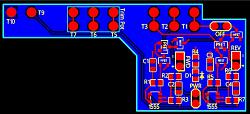
After setting up the drive, I made a quick and dirty manual control panel out of a short piece of galvanised right angle, bent it downward a bit to make it more comfortable to use and then installed it next to the MEM starter box that's the safety disconnect between mains power and the drive.
Once that was done I changed tack and focused on swarf control. For that I used some salvaged polycarbonate sheeting (more discardings salvaged from work) and walled off the bench underneath to prevent chips collecting on the shelf below where the drive and motor are housed.
The motor is well sealed, bar the air intake round back. The holes are easily big enough to suck chips through, so I took to bending out and flattening the rim of an old perforated aluminium speaker on my vice with a hammer and glued it over the intake. Still plenty of air movement but much reduces the chance of chips getting in.
With that done I set about mounting the drive as close to the control panel as I could get it. After many iterations on the same theme, the favoured combo was some medium size t slot profile, a heavy duty bracket and a short length of mounting rail.
During a quick tea break, I orderd a pulley for the new motor as the shaft is a lot bigger than the old one. I did consider boring out the old pulley but it was worn so thin it wouldn't have survived a gear puller.
I also ordered a new drive pulley for the lathe while I was at it. The original iron pulley casting is out of balance and causes a lot of vibration at certain speeds. It's also damaged, two of the support struts are cracked right through so there was no getting round it.
With the pulleys ordered, I turned my attention back to the control panel as it looked rather exposed. As luck would have it, the top half of an enclosure from some electronic item or other was in my "doner" materials bin which looked a close enough size to use.
I first made sure it was oriented so the side with the flange would remain with the parts I wanted to keep so I could add a side panel later, I then marked and cut two slots with my angle grinder and dremel to fit round the switch and trim pots fixings underneath.
After that, I transferred some measurements from the control panel to the enclosure half, rough cut it a little over size and then filed it to dimention.
Once that was done, I took the other section and drew the two halves together to make a shorter version of itself and glued them together with superglue.
It was then black to control panel for marking and drilling four mounting holes for the new panel front, I then lined them both up and used a fine tip marker through the holes to mark their location on the front panel and drilled them out and fixed the two together with some short length course threaded screws.
I couldn't find any more sheet metal to make a side panel with at that point, so instead, I knocked up door for the front of the bench out of the left over polycarbonate sheet, no point going to all that trouble earlier only to leave that area wide open to swarf.
I had to cut the top right corner of the cover out to go round MEM box and control panel and used the offcut to make the missing side panel. After which a gave up tinkering as it was very late and I had to go to bed.
Next morning I remembered I had a door magnet stashed from ages ago, so after my first cup of tea, I went in search of it and eventually dug it out.
I then fixed the magnet as central as my eyes could deturmin, put a metal plate for the door on the magnet, put superglue on the plate and held the door closed applying pressure directly over them both till the glue set.
The hinges had to be extended out a bit so the door would lie flat when closed but it left a slight gap running along the top which was of minor concern.
Luckily we'd got some new curtains for the goods in entrance that were too long and needed trimming, So I grabbed a few and made a skirt to cover the gap in the door.
I'd made the cutout in the door too deep on purpose as the plan was to use a soft material that would flex around the MEM box a piece of those curtains was just the ticket.
Which brings us to the end of my adventures for the moment. I have to wait till next week for the pulleys to arrive and other shenanigans as I'm away the weekend, so for now, stay safe, stay happy and keep those chips flyin'


 LinkBack URL
 About LinkBacks


 Reply With Quote



Bookmarks