Free 186 More Best Homemade Tools eBook:  
Get tool plans

User Tag List

Page 1 of 2 1 2 LastLast
Results 1 to 10 of 15

Thread: Need suggestions on boring some plastic wheels to a larger bore in quantity

  1. #1
    Supporting Member KustomsbyKent's Avatar
    Join Date
    Dec 2014
    Location
    South Dakota
    Posts
    249
    Thanks
    2,501
    Thanked 185 Times in 110 Posts

    KustomsbyKent's Tools

    Need suggestions on boring some plastic wheels to a larger bore in quantity

    Hey guys,
    I'm looking for suggestions on boring out the center of some plastic wheels to a larger bore.

    Background:
    2 types of wheels, a 8" outer diameter, and a 5" outer diameter. The wheels are a Polyurethane core with a soft perimeter. They come with a 1.188" bore for an unsealed roller bearing.
    I am boring them out on both sides to accept a 1.375" OD sealed ball bearing, 2 per wheel.
    I have successfully chucked these into a 4 jaw chuck using dial indicator to zero the runout, and machine out one side, then flip it over and do the other side. I typically machined each bore to about 1.368 to 1.372 so the bearing fit fairly tight. I did the first 24 wheels this way... but it's slow. Because of the soft outer layer of the wheel, tightening the 4-jaw chuck down to zero runout is time consuming. The actual machining is fairly quick.

    Looking to optimize, I ordered a set of adjustable reamers, and just got those. I tried them the other night on a single wheel, and it works, but is slower. I had to use 2 of the adjustable reamers. Starting with the smaller reamer, I locked it in the vice, adjusted it until it was just starting to cut, and then turned the wheel by hand down onto the reamer. Adjusting it larger, and doing again & again & again, until that reamer was maxed out. Then I switched out to the larger reamer, and crept up on the final size.
    It didn't require any specialized equipment, resulted in a nice finish, and the bearing fit well, but it took even longer than machining them.

    Future looking, I will need to do more of these wheels in batches of 24, in a mix of 8" and 5" wheels.

    What are your suggestions for doing this quicker/easier? You can't take off too much material at one time, as the material is a bit spongy so it flexes as you machine. Small cuts seems to work the best. Holding these is a problem with the soft outer portion. They are also not perfectly concentric from center to outer diameter, but it's not critical since this is all a low speed final application.... 7 mph.

    Thanks
    Kent

    186 More Best Homemade Tools eBook

  2. #2
    Supporting Member Frank S's Avatar
    Join Date
    Aug 2015
    Location
    Peacock TX
    Posts
    11,638
    Thanks
    2,189
    Thanked 9,137 Times in 4,367 Posts

    Frank S's Tools
    Quote Originally Posted by KustomsbyKent View Post
    Hey guys,
    I'm looking for suggestions on boring out the center of some plastic wheels to a larger bore.

    Background:
    2 types of wheels, a 8" outer diameter, and a 5" outer diameter. The wheels are a Polyurethane core with a soft perimeter. They come with a 1.188" bore for an unsealed roller bearing.
    I am boring them out on both sides to accept a 1.375" OD sealed ball bearing, 2 per wheel.
    I have successfully chucked these into a 4 jaw chuck using dial indicator to zero the runout, and machine out one side, then flip it over and do the other side. I typically machined each bore to about 1.368 to 1.372 so the bearing fit fairly tight. I did the first 24 wheels this way... but it's slow. Because of the soft outer layer of the wheel, tightening the 4-jaw chuck down to zero runout is time consuming. The actual machining is fairly quick.

    Looking to optimize, I ordered a set of adjustable reamers, and just got those. I tried them the other night on a single wheel, and it works, but is slower. I had to use 2 of the adjustable reamers. Starting with the smaller reamer, I locked it in the vice, adjusted it until it was just starting to cut, and then turned the wheel by hand down onto the reamer. Adjusting it larger, and doing again & again & again, until that reamer was maxed out. Then I switched out to the larger reamer, and crept up on the final size.
    It didn't require any specialized equipment, resulted in a nice finish, and the bearing fit well, but it took even longer than machining them.

    Future looking, I will need to do more of these wheels in batches of 24, in a mix of 8" and 5" wheels.

    What are your suggestions for doing this quicker/easier? You can't take off too much material at one time, as the material is a bit spongy so it flexes as you machine. Small cuts seems to work the best. Holding these is a problem with the soft outer portion. They are also not perfectly concentric from center to outer diameter, but it's not critical since this is all a low speed final application.... 7 mph.

    Thanks
    Kent
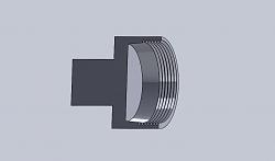
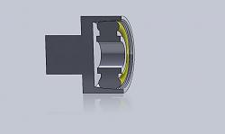
    Make you a holder for your wheels that the wheel will fit in but the bore of the hollow arbor has a few degrees taper thread the inside of the straight part of the bore and an internal nut with a large enough bore to allow your boring bar to bore the center of the wheel
    the arbor would look something like this then you could use your 3 jaw if you wanted to because you never touch the chuck just remove the nut and insert another wheel
    You would have to make one for each size but if you have more than a very few it is worth the time Just find a piece of pipe weld a back plate to it weld a shaft or if your chuck is large enough chuck on the perimeter without the need
    for a stub shaft You may even find a pipe nipple and cap near the size you require then just bore to suit . The threads on the fixture need not be internal but then it would rewuire a cap nut and spacer to tighten on the wheel's sides

    Need suggestions on boring some plastic wheels to a larger bore in quantity-urathane-wheel-collet.jpg
    Need suggestions on boring some plastic wheels to a larger bore in quantity-wheel-collet.jpg

    2,000+ Tool Plans
    Last edited by Frank S; Nov 23, 2021 at 11:59 PM.
    Never try to tell me it can't be done
    When I have to paint I use KBS products

  3. #3
    Supporting Member KustomsbyKent's Avatar
    Join Date
    Dec 2014
    Location
    South Dakota
    Posts
    249
    Thanks
    2,501
    Thanked 185 Times in 110 Posts

    KustomsbyKent's Tools
    Thanks Frank! Pipe chunks that large aren't readily available where I am. I wonder if I could make that outer band portion out of plywood, and slit it multiple times around the perimeter so it's like a collet, and then use a hose clamp to cinch it around the wheel?

  4. #4
    Supporting Member
    Join Date
    Mar 2013
    Location
    Perth Western Australia
    Posts
    78
    Thanks
    25
    Thanked 71 Times in 28 Posts

    Peter Sanders's Tools
    Hi Kent

    It does not have to be a pipe section etc. If your lathe has the capacity and the wheels and centres are concentric (which I assume they are), you could just machine a suitable recess in a flat plate and weld on some clamping lugs. The clamping lugs would clamp the wheel to the face of the plate, via clamping "arms" not clamping around the circumference, two or three would be sufficient. I'd consider a recess of 4-6 mm is sufficient to position the wheel securely as there is not too much weight involved and this weight is evenly distributed.

    If you are smart, you could create TWO recesses in the plate and cater for both size wheels. Perhaps 6 mm for the 8" wheel and 12 mm for the 5" wheel. That way you only ever have to set up the "jig" once to turn as many wheels as you need. With some thought you could utilise the same clamp arms and lugs to clamp both size wheels. If you want some thoughts on "design" let me know.

    Align the recess to the lathe centre and insert the wheel, clamp, bore, unclamp, flip around, clamp, bore other side and release.

    Regards

    Peter

    Afterthought...

    Weld the lugs on first, probably just two lugs to allow convenient positioning in a four jaw chuck. Make the recesses 4 mm for the 8" wheel, another 4 mm deeper for the 5" wheel and using a 12 mm thick plate there would be 4 mm left so the wheels don't fall through :-)

    Afterthought two...

    After rereading your post and jumping down from my conclusion, perhaps my suggestion was not appropriate. The conclusion I jumped to was thinking about plastic disks, not real "wheels", sorry about that :-)
    Last edited by Peter Sanders; Nov 24, 2021 at 11:26 PM.

  5. #5
    Supporting Member desbromilow's Avatar
    Join Date
    Aug 2012
    Location
    Australia
    Posts
    801
    Thanks
    527
    Thanked 362 Times in 207 Posts

    desbromilow's Tools
    Quote Originally Posted by KustomsbyKent View Post
    Thanks Frank! Pipe chunks that large aren't readily available where I am. I wonder if I could make that outer band portion out of plywood, and slit it multiple times around the perimeter so it's like a collet, and then use a hose clamp to cinch it around the wheel?
    hell yes - you're approaching the same problem the wood turners face with large hollow bowls. They make up a chuck with wooden sides, and then simply have a face" washer" which has bolts through to the backing plate - imagine a drum or banjo with the work piece inside, and a hole in the top so you reach in and access the work piece.

  6. #6
    Supporting Member hemmjo's Avatar
    Join Date
    Feb 2017
    Posts
    2,665
    Thanks
    251
    Thanked 1,515 Times in 855 Posts

    hemmjo's Tools
    Yep, plywood is tougher than the plastic. I am curious what you are building!! is it top secret of are you going to show us ?

  7. #7
    Supporting Member Frank S's Avatar
    Join Date
    Aug 2015
    Location
    Peacock TX
    Posts
    11,638
    Thanks
    2,189
    Thanked 9,137 Times in 4,367 Posts

    Frank S's Tools
    Kent, I'll be first to admit that I am not a wood guy. In my way of thinking the best use for wood is to heat my house with, But to expand on your idea of a possible wooden collet, think about using a 3 jaw scrolling chuck if it has removable top jaws. glue layers of plywood or possibly MDF like you mentioned turn out the profile to fit the wheels quite possibly a profile for both sizes but I should think the depth would be too deep to accomplish this. Before hollowing out the profile though cut the slab into 3 pie shaped pieces mill what would become the back side to resemble the mounting lugs on the top jaws drill and counter drill the holes for mounting Remove your top jaws mount the 3 pieces on your chuck and you now have a set of soft jaws which you can cut any profile into you desire. I would prefer making them out of Aluminum but there is no reason why plastic MDF or plywood wouldn't work the same way Just mill the mounting profile so the soft jaws rest lightly against the chuck face when bolted to the jaws. My mill is down or I would be happy to make a set for you if you were to send me a 3 jaw chuck to match the soft jaws to.
    Never try to tell me it can't be done
    When I have to paint I use KBS products

  8. The Following User Says Thank You to Frank S For This Useful Post:

    KustomsbyKent (Nov 28, 2021)

  9. #8
    Supporting Member bruce.desertrat's Avatar
    Join Date
    Nov 2017
    Posts
    809
    Thanks
    592
    Thanked 687 Times in 369 Posts

    bruce.desertrat's Tools
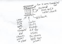
    I would make a wooden (MDF would work well for this) 'chuck' for each sized wheel.

    Basically a stack of a stub for the lathe chuck to hold glued and screwed to a circular plate comfortably larger than the outer diamerter of the wheel

    Glued to that is a ring with the same outside diameter and an inside diameter sized to a tight fit with the wheel. This ring should be just a little thinner than the width of the wheel. (depending on the thickness of the MDF, you might have to glue up a couple thicknesses)

    Finally there is a separate ring with a inner diameter that allows access to the center for boring, but is smaller than the wheels diameter. This is a separate piece.

    This whole thing can be cut out of the sheet with a jigsaw, then assembled and trued to final diameters inside and out on the lathe to center it.

    In use, the wheel to be bored is stuck inside the glued-up rings, then the loose ring bolted down to hold the wheel tightly in place. Bore out the hub, unbolt the retainer ring, pull out the wheel and go to the next one.

    Attached is a badly drawn sketch of the assembly from the side.

    Need suggestions on boring some plastic wheels to a larger bore in quantity-scan.jpeg

  10. The Following User Says Thank You to bruce.desertrat For This Useful Post:

    KustomsbyKent (Nov 28, 2021)

  11. #9

    Join Date
    Aug 2020
    Posts
    1
    Thanks
    5
    Thanked 0 Times in 0 Posts
    Have you tried freezing the wheels and working them cold. I've done this before for UHMW wheels. Throw them in the freezer over night and then they are not as mushy. Never tried it but maybe use dry ice to freeze them faster.

  12. #10
    Supporting Member hemmjo's Avatar
    Join Date
    Feb 2017
    Posts
    2,665
    Thanks
    251
    Thanked 1,515 Times in 855 Posts

    hemmjo's Tools
    Quote Originally Posted by bruce.desertrat View Post
    I would make a wooden (MDF would work well for this) 'chuck' for each sized wheel.
    ...snip... Click image for larger version. 

Name:	Scan.jpeg 
Views:	138 
Size:	140.6 KB 
ID:	41101
    Or attach Bruce's idea to a face plate to machine the cavity to fit the wheels.

  13. The Following User Says Thank You to hemmjo For This Useful Post:

    bruce.desertrat (Nov 29, 2021)

Thread Information

Users Browsing this Thread

There are currently 1 users browsing this thread. (0 members and 1 guests)

Tags for this Thread

Bookmarks

Posting Permissions

  • You may not post new threads
  • You may not post replies
  • You may not post attachments
  • You may not edit your posts
  •