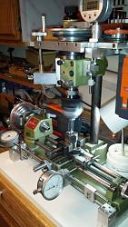
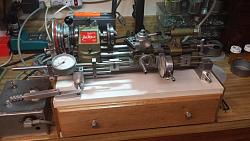
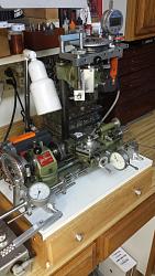
The HomemadeTools.net article by Rick Sparber “Aligning the X axis Leadscrew on a RF-30” reminded me of some of the adjustments I made to my old Unimat SL 1000 lathe when I added a vertical milling head. Like Rick’s work my adjustments required aligning all six different parameters for X, Y, Z, roll, pitch, and yaw.
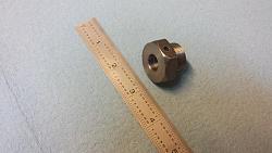
The fixed rod supports for the x and y lathe ways proved to be a challenge because the rods are supported in a die cast lathe bed. A combination of twisting the cast bed and adding opposing set screws to a cross slide way rod (see photo of taping screw holes) brought this into alignment. It is essential to align the x and y-axes orthogonal to the lathe cabinet before adding the vertical column for the milling head. All axes were less than 0.003" out of alignment and required very slight and iterative changes to bring everything into alignment.
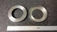
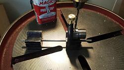
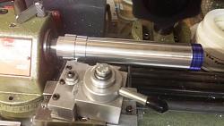
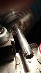
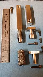
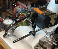
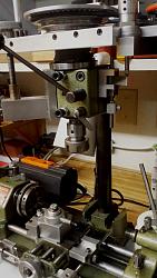
Adding the new z-axis dimension with a milling head column and column support required the most iterative process to bring the x, y and z axis into orthogonal alignment with each other. The milling column attachment base was made from 3”x12”x1” aluminum bar and bolted to the lathe cabinet. The vertical column support base was machined flat and square on my mini lathe using a custom mandrel, and then removed and bolted to the aluminum attachment base. The milling support base has a 0.0015” thick shim that brings the vertical column orthogonal to the lathe x and y-axes (the shim is shown in the 9th photo below). The last photo shows tramming left to right rotational adjustment of the milling head to be parallel with the lathe ways support rods. The photos below show some of the measurements and adjustments that were made during the alignment processes.


 LinkBack URL
 About LinkBacks


 Reply With Quote





Bookmarks