Free 186 More Best Homemade Tools eBook:  
Get tool plans

User Tag List

Results 1 to 5 of 5

Thread: Mini Lathe DRO Issues

  1. #1
    Supporting Member
    Join Date
    Mar 2017
    Location
    Colorado, USA
    Posts
    42
    Thanks
    24
    Thanked 107 Times in 30 Posts

    dgbreggin's Tools

    Mini Lathe DRO Issues

    I purchased 3 of these "DRO" units (with the appropriate parts kits) for my mini lathe. (No affiliation.) These are inexpensive, chinese-made items.

    https://www.littlemachineshop.com/pr...gory=132430212

    I have two issues with these. They both involve "zero" on the readout.

    First is when I try to use the zero to return to a position. When I press the "zero" button to set the zero, withdraw the tool, then try to return to zero, it does not return to the same location. It is off by about 1/2 thou. (This is after compensating for lash by overtravel and using consistent direction of rotation of the crank.)

    Second is related to zero on the display. You would expect that moving the cross slide from DRO 0.001 to -0.001 inches would move the cross slide 0.002 inches but it actually moves 0.003 inches. Same behavior when using mm instead of inches. Same behavior when moving from -0.001 to 0.001 inches. Again, this is not an issue of lash. All measurements were taken while turning the screw in the same direction.

    It is as if there is both a +0 and a -0 internal to the DRO. There is no -0 on the display, but 0 shows for about 0.002 inches of travel.

    Has anyone else seen this? Does anyone have a useful workaround, particularly for the first case?

    186 More Best Homemade Tools eBook

  2. #2
    Supporting Member Toolmaker51's Avatar
    Join Date
    Feb 2016
    Location
    Midwest USA
    Posts
    5,334
    Thanks
    7,044
    Thanked 3,011 Times in 1,900 Posts

    Toolmaker51's Tools
    DRO's count on 2 parameters other than units set for. Those are repeatability and resolution. Repeatability is just as it sounds. Perform a simple test, using a travel indicator; touch off - observe readings - and repeat a few times, both + & - z
    Should those be consistent, the likelihood of scale mounting not sufficiently parallel to the axis being measured, is first one suspect.

    Resolution is a different issue. Compare a .001 and .0001 vernier micrometer. We can interpolate readings that split .001 observing position of barrel to thimble, but discretion comes into play, is it .2003 or .2004? On a vernier scaled mic we are more sure of fourth digit, leads to estimating the fifth.

    DRO's are faced with same, but are interpolating ALL the time, any position other than directly on a particular increment. So, that is 'built into' a scale, an intended resolution. Some readouts have a switch to shut-off display of last increment. Most DRO are 1/2 thou, but they are available in much finer increments,
    using highest grade elements that discern (read) increments AND interpolate those in between. (i.e.) A .001 scale doesn't register next increment until crossing the 5th or 6th tenth, it is a quality result of manufacture, potential temperature differential and others less tangible factors. The instructions should cover those.

    The other is response speed, few readouts can power up and switch increments equal to feed rate.

    2,000+ Tool Plans
    Last edited by Toolmaker51; Feb 28, 2023 at 07:36 PM.
    Sincerely,
    Toolmaker51
    ...we'll learn more by wandering than searching...

  3. The Following User Says Thank You to Toolmaker51 For This Useful Post:

    tooly (Feb 28, 2023)

  4. #3
    Supporting Member
    Join Date
    Sep 2018
    Posts
    2,346
    Thanks
    11,132
    Thanked 1,219 Times in 664 Posts

    nova_robotics's Tools
    No idea about these units, but I was having problems with the DRO on my mill. I pulled the encoders apart and soldered decoupling capacitors across power and ground.

  5. #4
    Supporting Member
    Join Date
    Mar 2017
    Location
    Colorado, USA
    Posts
    42
    Thanks
    24
    Thanked 107 Times in 30 Posts

    dgbreggin's Tools
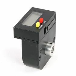
    This is the "DRO" unit I am having issues with. It is battery powered, and it is not a linear scale but a rotary one. It measures crank revolutions.

    Mini Lathe DRO Issues-5673.480.jpg

    Toolmaker51: I understand all that you posted, but none of it applies to my issues / questions.

    Let me describe this in more detail, apologies for the long post.

    The errors I describe occur very repeatably within a few tenths. I have made these measurements multiple times, probably about 30 or 40. I have used several indicators, including a DTI with 0.0001 resolution. Both of the scenarios were encountered on 4 separate "DRO" units on 3 separate parts of the lathe (cross slide, compound slide, tailstock quill). Results from each are statistically indistinguishable.
    Measurements for the cross slide and compound slide were made against a piece of hex stock in the chuck. I would turn the stock slightly to verify the peak value of each measurement. Tailstock measurements were made against the end of a faced piece of stock. All measurements of a set were made while turning the crank in the same direction to nullify any lash. All measurements were made with the lathe off (not running).


    Scenario 1:

    Wind in to a certain point, press the "zero" button, zero the DTI, wind out, wind back in until the "DRO" reads zero, the DTI consistently about 0.0004 to 0.0005 inches. If I wind in to a non-zero number, say 0.050, zero the DTI, wind out, then wind in again to 0.050, the discrepancy is consistently less than 0.0001 inches.


    Scenario 2:

    Wind in to a point, press the "zero" button, wind out, wind back in until the display is 0.002 inches. Set the DTI to 0.0020 inches. Wind in slowly measuring the DTI vs. the "DRO". These are the numbers:

    DTI: DRO:
    0.0020 0.002
    0.0010 0.001
    0.0000 0.000
    -0.0010 0.000
    -0.0020 -0.001
    -0.0030 -0.002
    -0.0040 -0.003

    All measurements within +/- about 0.0001 inches.


    Additional:

    Both of these scenarios can be repeated while turning the crank "out" as well as "in" as described above. In each case, all measurements were made while turning the crank in the same direction.

    I did explain all this to LMS. They said they would contact the manufacturer. I never heard back from them.

    I really do understand why both of these are happening. Scenario 1 is related to rounding off the display. Scenario 2 is related to poor programming of the firmware. What I am looking for is a workaround or a simple way to compensate for these issues.

    Any suggestions appreciated.

  6. The Following User Says Thank You to dgbreggin For This Useful Post:

    Toolmaker51 (Feb 28, 2023)

  7. #5
    Supporting Member Toolmaker51's Avatar
    Join Date
    Feb 2016
    Location
    Midwest USA
    Posts
    5,334
    Thanks
    7,044
    Thanked 3,011 Times in 1,900 Posts

    Toolmaker51's Tools
    Admittedly, didn't follow link to LittleMachineShop. Familiar with them, the Feed-Speed and Tapping Calculators are bookmarked on PC & phone.

    Faced with same dilemma, initial route would depend on a carriage stop.
    Before DRO's and Trav-A-Dial, we did this;
    Ink pen a mark across strip of masking tape, attach across edge of compound slide and where it runs. That is a reliable index for which dial setting you wish to return, or progress in relation to threading. Same idea works on carriage handwheel, and dial collar, sometimes cross slide too.

    Then and for time being, calculate the average discrepancy of readout to actual carriage movement, use it to approximate position of successive passes, then take measurements to set that feature in accord with dependable instruments.

    My guess is play in handwheel shaft and bushings, which may include pitch errors in drive gear and rack.

    I'd also remind LMS of dissatisfaction with that product; if there is no evidence of backlash, play or irregularities in the associated machine parts. Your description is clear enough, without witnessing first hand, it's a shot in the dark.


    2,000+ Tool Plans
    Last edited by Toolmaker51; Mar 1, 2023 at 12:00 AM.
    Sincerely,
    Toolmaker51
    ...we'll learn more by wandering than searching...

  8. The Following User Says Thank You to Toolmaker51 For This Useful Post:

    dgbreggin (Mar 1, 2023)

Thread Information

Users Browsing this Thread

There are currently 1 users browsing this thread. (0 members and 1 guests)

Bookmarks

Posting Permissions

  • You may not post new threads
  • You may not post replies
  • You may not post attachments
  • You may not edit your posts
  •