Free 186 More Best Homemade Tools eBook:  
Get tool plans

User Tag List

Page 1 of 2 1 2 LastLast
Results 1 to 10 of 11

Thread: Mill Z axis crank wheel

  1. #1
    Supporting Member Bony's Avatar
    Join Date
    May 2015
    Location
    Tasmania, Australia
    Posts
    381
    Thanks
    63
    Thanked 184 Times in 66 Posts

    Bony's Tools

    Mill Z axis crank wheel

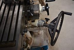
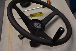
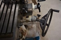
    This idea came to me when I had to make repeated small increments to the depth of milling a part. The wheel is an inexpensive steering wheel from a power boat, found in any boating/marine/ship chandlers shop. The rim of the wheel is always just at hand, rather than fumbling for the crank and if you chose a steering wheel of larger radius than the crank handle (normally supplied with a small mill) very small height adjustments to the mill table are much easier to make. In addition it's also easier to lift the table with minimum effort when its loaded up.

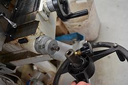
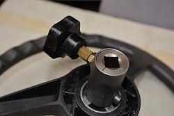
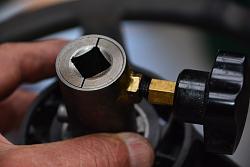
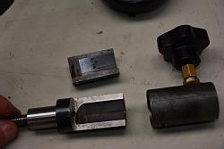
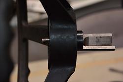
    The solution for attaching the wheel to the square shaft on the mill is to made the female part in two halves, and to fasten it with a simple knob which forces the halves together onto the shaft.

    I hope the photos show all that you'll need to make one for yourself.

    Mill Z axis crank wheel-wheel1.jpgMill Z axis crank wheel-wheel2.jpgMill Z axis crank wheel-wheel4.jpgMill Z axis crank wheel-wheel5.jpgMill Z axis crank wheel-wheel6.jpgMill Z axis crank wheel-wheel7.jpgMill Z axis crank wheel-wheel8.jpg

    Feel free to email me if you need further explanation. All the dimensions and way you proceed will depend on the materials you have at hand and the size of your mill, and sorry I don't have any drawings.

    186 More Best Homemade Tools eBook

  2. The Following 11 Users Say Thank You to Bony For This Useful Post:

    bigtrev8xl (Mar 30, 2017), Gary A. Wills (Mar 18, 2018), Jon (Mar 19, 2016), kbalch (Mar 20, 2016), Lance Maskell (Mar 30, 2017), Manitoba Man (May 21, 2021), mwmkravchenko (Feb 8, 2018), Paul Jones (Mar 31, 2017), rctoywizard (Mar 22, 2016), Scotty12 (May 28, 2020), Toolmaker51 (Mar 29, 2017)

  3. #2

    Join Date
    Dec 2015
    Location
    Groton NH USA
    Posts
    13
    Thanks
    24
    Thanked 2 Times in 2 Posts
    Very cool idea!
    I put a Go Kart stearing wheel on my 23" arbor press for the left side. Helped me out a ton too.
    I got to try your idea.
    Thanks again

    2,000+ Tool Plans

  4. #3
    Supporting Member Toolmaker51's Avatar
    Join Date
    Feb 2016
    Location
    Midwest USA
    Posts
    5,334
    Thanks
    7,044
    Thanked 3,011 Times in 1,900 Posts

    Toolmaker51's Tools
    If there is clearance, I'll try a flat motor bus wheel and a spinner knob or folding tapered handle. My K&T was built with one, yet never thought of affixing that human engineering elsewhere! Ergonomics are a real aide to us so aged.
    Sincerely,
    Toolmaker51
    ...we'll learn more by wandering than searching...

  5. The Following User Says Thank You to Toolmaker51 For This Useful Post:

    Paul Jones (Mar 31, 2017)

  6. #4
    Supporting Member tonyfoale's Avatar
    Join Date
    Nov 2016
    Location
    Spain
    Posts
    1,607
    Thanks
    721
    Thanked 2,706 Times in 726 Posts

    tonyfoale's Tools
    For anyone who wants to attach an alternative winding device to a Bridgeport here are the important dimensions for making a mating thingy.

    Mill Z axis crank wheel-bridgeport-knee-handle.jpg

    I did the ultimate in geriatric aids, I added a motor, so the extent on my effort has reduced to setting a direction switch and pressing a button. No good for precision adjustment but the Bridgeport has the quill for that, and I did it to be able to still use the handle. Always seeking the easy way I also added some helper springs as in my previous post at http://www.homemadetools.net/forum/k...5951#post82823 which really makes the effort minimal.

  7. The Following 2 Users Say Thank You to tonyfoale For This Useful Post:

    Paul Jones (Mar 31, 2017), Toolmaker51 (Mar 30, 2017)

  8. #5
    Supporting Member Toolmaker51's Avatar
    Join Date
    Feb 2016
    Location
    Midwest USA
    Posts
    5,334
    Thanks
    7,044
    Thanked 3,011 Times in 1,900 Posts

    Toolmaker51's Tools
    Tony's powered knee and gas spring load reduction makes me wonder...Lathes and jigbore foundation of accuracy is due to the ways. Knee ways have 2-4x bearing surface of lathe carriages. A vari-drive DC motor driving a reduction gear could be a dynamite modification. For starters, many have roughed a bore cranking manually in lathes or mills. The only difference would be figuring IPM [inch per minute] vs. FPR [feed per revolution]. Knee mills are limited to something like .001 to .006 per rev. Good for small holes to maybe 5", with standard tooling. Powering the knee would mean infinite range more or less, especially in proper finish. Many an occasion required a lathe, when labor-wise setting a mill for multiple parts would be the edge.
    Tony's adapter even makes it portable.

    P.S. edit. I've seen one occasion of an energetic young 2nd shift operator + cordless drill vs knee of a turret mill. He has spotty mechanical ability; injudicious in application of rpm, not to mention clamped directly in the chuck, sans adapter to apply torque. The job needed many Z changes.
    In three days hand-crank wouldn't fit the shaft. After dressing equivalent pipewrench marks off, the lead screw/ nut combination were found to be scored beyond accurate use, in same range of the three days work. Repair cost exceeded the initial profit of labor saved by 500%.
    Last edited by Toolmaker51; Mar 31, 2017 at 06:41 PM. Reason: An uh-oh recollection
    Sincerely,
    Toolmaker51
    ...we'll learn more by wandering than searching...

  9. The Following User Says Thank You to Toolmaker51 For This Useful Post:

    Paul Jones (Mar 31, 2017)

  10. #6
    Supporting Member tonyfoale's Avatar
    Join Date
    Nov 2016
    Location
    Spain
    Posts
    1,607
    Thanks
    721
    Thanked 2,706 Times in 726 Posts

    tonyfoale's Tools
    Quote Originally Posted by Toolmaker51 View Post
    Tony's powered knee and gas spring load reduction makes me wonder....... A vari-drive DC motor driving a reduction gear could be a dynamite modification. .................
    Tony's adapter even makes it portable.
    Actually, the adaptor drawing is not mine, I found it on the net and it was designed to be used with a cordless drill. For me it was just a nice reference for the dimensions of the Bridgeport dogs.
    I intended to make the motor drive through the dogs but then I saw how I could fix a pulley behind them and still retain the ability to use the original handle if I needed to make a fine adjustment. Perhaps I should take some photos and make a post

    I am using a DC motor but I decided that single speed was enough so I feed it through a step down transformer, which I had, with a bridge rectifier between motor and transformer. The speed could be a little higher but that is what the transformer provides and in any case it is far quicker that winding by hand. Having used it for a couple of years now I am quite happy with a single speed, and have never needed to use the manual handle.

    I would highly recommend some form of counter balancing the weight of the knee and table. It is a win/win modification. For a small mill I'd use an actual counter weight with a cable over a pulley, that enables you to exactly balance the weight throughout the movement range making moving the knee assembly effortless whether manual or motorized. It is easy enough to cast a concrete lump for the counterweight, throw in any steel or lead scrap to reduce the needed size. I use counter weights on a couple of drill presses which don't have a rack and pinion. However, that is hardly practical with mills of the Bridgeport's size, hence my use of the pneumatic spring units which give reduced help as they become extended (table raised), but owt's better than nowt.
    Last edited by tonyfoale; Mar 31, 2017 at 03:26 AM. Reason: Correct spelling

  11. The Following User Says Thank You to tonyfoale For This Useful Post:

    Toolmaker51 (Mar 31, 2017)

  12. #7
    Content Editor
    Supporting Member
    DIYer's Avatar
    Join Date
    Aug 2013
    Posts
    3,055
    Thanks
    793
    Thanked 1,888 Times in 1,683 Posts


    Thanks Bony! We've added your Z Axis Crank Wheel to our Machining category,
    as well as to your builder page: Bony's Homemade Tools. Your receipt:


  13. #8
    Supporting Member Toolmaker51's Avatar
    Join Date
    Feb 2016
    Location
    Midwest USA
    Posts
    5,334
    Thanks
    7,044
    Thanked 3,011 Times in 1,900 Posts

    Toolmaker51's Tools
    Quote Originally Posted by tonyfoale View Post
    Actually, the adaptor drawing is not mine, I found it on the net and it was designed to be used with a cordless drill. For me it was just a nice reference for the dimensions of the Bridgeport dogs...
    I would highly recommend some form of counter balancing the weight of the knee and table. It is a win/win modification. For a small mill I'd use an actual counter weight with a cable over a pulley, that enables you to exactly balance the weight throughout the movement range making moving the knee assembly effortless whether manual or motorized. It is easy enough to cast a concrete lump for the counterweight, throw in any steel or lead scrap to reduce the needed size. I use counter weights on a couple of drill presses which don't have a rack and pinion. However, that is hardly practical with mills of the Bridgeport's size, hence my use of the pneumatic spring units which give reduced help as they become extended (table raised), but owt's better than nowt.
    A counter-weight is feasible. In use by variety of machine tools; especially in sliding heads of jigbores and drills like the Cleereman, operating in the hollow columns. They use a sprocket and 1 or 2 rows of roller chain connected at the upper end of head, weight of course at other end.
    None are neutral or weight cancelling, just reduction so the head doesn't float upward.
    In the case of a leadscrew raising a machine element, the same principle would apply. Less effort is nice; still want a leadscrew to bear load for backlash compensation. Otherwise the dial or readout will be useless. Lazy google search indicates a 9 x 30 knee & table at 400-460 lbs, 10 x 54's at 500. Seems reasonable target, considering weight of vises, rotabs, indexers etc. Designed load on 9 x 30 is 750lb workpiece.
    A pair of flanged bearings outside the column would support a shaft and sprockets through it. They have self aligning feature built in. Place high enough for full upward travel.
    A pair of standoffs on the knee would anchor the roller chain. That would ensure upper end of knee contacts column, leverage presses lower end into contact. Place high enough so a pair of weights operate without contacting machine base or floor.
    Last edited by Toolmaker51; Apr 1, 2017 at 10:27 AM. Reason: Ongoing counterweight visualization...
    Sincerely,
    Toolmaker51
    ...we'll learn more by wandering than searching...

  14. #9
    Supporting Member Toolmaker51's Avatar
    Join Date
    Feb 2016
    Location
    Midwest USA
    Posts
    5,334
    Thanks
    7,044
    Thanked 3,011 Times in 1,900 Posts

    Toolmaker51's Tools
    And there was another way; moving heavy machine elements. A gullible apprentice.
    "Crank this while I observe _ _ _ _ " [insert any excuse here].
    Sincerely,
    Toolmaker51
    ...we'll learn more by wandering than searching...

  15. #10
    Supporting Member Gary A. Wills's Avatar
    Join Date
    May 2015
    Posts
    25
    Thanks
    15
    Thanked 14 Times in 9 Posts
    Probably cheaper then machine hand wheel. I like it good job , love thinking out of the box. Thanks

Thread Information

Users Browsing this Thread

There are currently 1 users browsing this thread. (0 members and 1 guests)

Tags for this Thread

Bookmarks

Posting Permissions

  • You may not post new threads
  • You may not post replies
  • You may not post attachments
  • You may not edit your posts
  •