In my recent post about fly cutters at http://www.homemadetools.net/forum/d...y-cutter-63995 I showed a photo of the fly cutter being checked for balance on a tool that I had made. I thought that I had posted that tool on this forum previously but when I searched I couldn't find it. Aging memory problem. I had posted it on some motorcycle Facebook forums.
To avoid rewriting it just for this tool forum I present just as it was elsewhere. Although made for a specific type of crankshaft I have used this tool for balancing many other things, as for example the fly cutter.
Background.
I have never liked the usual crank alignment methods of either supporting the crank between centres or on V-blocks. A problem that I have always seen is that it is sometimes difficult to interpret exactly what the measurements mean. Regardless of the method used the alignment tolerances are usually quoted as the same but what you measure depends so much on the length of the shafts if between centres and the mounting position if on V-blocks.
I have often avoided these problems by mounting a single mainshaft in two bearings such that the crankshaft as a whole rotates about the axis of that mainshaft. Then any misalignment measured on the second mainshaft is a clear indication of what is wrong. However, for this method to have validity the main shaft must be a good fit in the supporting bearings with no play and this makes crank alignment rather slow because it takes too long to push the mainshaft into the bearings before checking and then removing it prior to attacking it with a lead or copper hammer to correct any misalignment.
For several years I have been intending to make a tool to enable me to locate a mainshaft without play but which was rapid to mount and dismount the crankshaft, but the task never bubbled up to the top of the pile of things to do now. That is until recently. For reasons of expediency I was trying to align an Aermacchi crank shaft between centres but nothing made sense. Runout measurements seemed incompatible. In desperation I made up a bearing holder to support the crank by a single mainshaft. Then the problem became quickly apparent, the other mainshaft was bent at the reduced diameter where the alternator attaches. I am guessing that sometime in its past it was dropped and landed on that shaft. The bearing mount part of the shaft was not bent and it was easy enough to get that aligned with the other shaft, and then it was clear that the runout at the alternator end of the shaft was close to 1mm. Of course that meant that the centre on that end of the shaft was out by the same amount, leading to the original alignment problems. This told me that it was time to make my long planned tool.
Implementation.
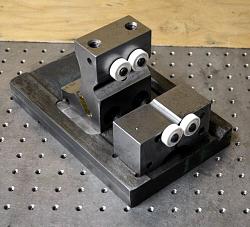
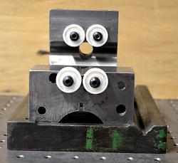
The idea is quite simple, I would mount two ball bearings close to one another to support and allow rotation of the bearing area of one mainshaft, similar in concept to that of static wheel balancing fixtures. However, the overhanging weight of the crankshaft requires an additional support force acting downward at the other end of that mainshaft. To handle that another pair of bearings is to be mounted above the end of the mainshaft. Now that mainshaft is forced to rotate about an axis through the centres of the supported journals. Insertion and removal of the crankshaft into the tool is simplicity itself and very fast. Measurements of runout on the other mainshaft give easy to interpret indications of the remedial actions needed to correct any errors.
This tool also seemed to be a good base to use for crankshaft balance factor determination and correction. However, good sensitivity for balance measurement requires the lowest possible friction in the bearings. Although regular unsealed steel ball bearings lubricated with very thin oil would probably work well enough for practical purposes, I choose to use modern ceramic bearings which have very low friction when run dry, as long as they are kept free of dust and dirt.
Although the tool featured here has been made as Aermacchi specific, it could just as easily be made to suit any other crankshaft. With a little more work the bearing mounting could be made adjustable for those who have need to use it for a range of crankshafts.
Click on the following pix. to see them full size.
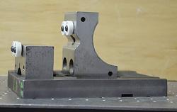
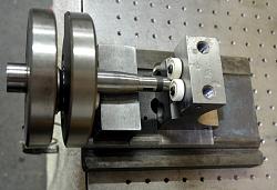
The solid framework was constructed from material lying around the workshop. The base is from the saddle of an old lathe and the two bearing mounting blocks were from some old tooling fixtures. Note the white colour of the ceramic bearings.
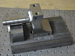
Shaft fitted to demonstrate how the bearings work to provide support. The extra holes and cutouts in the blocks are just a legacy of their previous life.
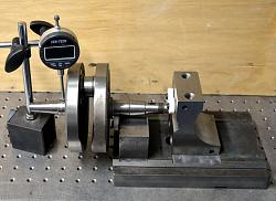
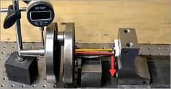
Crankshaft mounted in the tool for checking alignment. Runout can be checked at both extremities of the shaft and also on the flywheel face to check for parallelism between the two wheels.
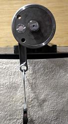
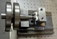
Crankshaft mounted for checking balance factor. The ease of mounting the crankshaft is clearly apparent.
Crankshaft mounted for checking balance factor. The ceramic bearings give a very high degree of sensitivity.


 LinkBack URL
 About LinkBacks


 Reply With Quote
 I would, however, make the rear assembly on a sliding carriage to facilitate different length shafts.


Bookmarks