Free 186 More Best Homemade Tools eBook:  
Get tool plans

User Tag List

Page 1 of 2 1 2 LastLast
Results 1 to 10 of 12

Thread: Making Tight Bends with Heavy Gage Wire

  1. #1
    Supporting Member rgsparber's Avatar
    Join Date
    Nov 2012
    Location
    Phoenix, AZ
    Posts
    1,324
    Thanks
    780
    Thanked 2,851 Times in 672 Posts

    rgsparber's Tools

    Making Tight Bends with Heavy Gage Wire

    I was inspired by the wire bending tool from "DIY Useful Ideas". His tool makes the bending of thick wire almost effortless. Due to the forces involved, the pins used to bend the wire have to be rather large in diameter. That also sets the radius of the bend. I thought it would be fun to figure out how to reduce this radius without reducing the diameter of the wire. A working model is presented but I invite readers to suggest refinements before I commit to the finished design.

    If you are interested, please see

    https://rick.sparber.org/WireBender.pdf

    Your comments are welcome. All of us are smarter than any one of us.


    Thanks,

    Rick

    186 More Best Homemade Tools eBook
    Rick

  2. The Following 6 Users Say Thank You to rgsparber For This Useful Post:

    bobs409 (Feb 11, 2020), DIYSwede (Feb 11, 2020), Jon (Feb 11, 2020), rebuilder1954 (Feb 13, 2020), Scotsman Hosie (Feb 20, 2020), Seedtick (Feb 12, 2020)

  3. #2
    Content Editor
    Supporting Member
    DIYer's Avatar
    Join Date
    Aug 2013
    Posts
    3,055
    Thanks
    793
    Thanked 1,892 Times in 1,687 Posts


    Thanks rgsparber! We've added your Wire Bender to our Metalworking category,
    as well as to your builder page: rgsparber's Homemade Tools. Your receipt:


    2,000+ Tool Plans
    New plans added on 12/16/2024: Click here for 2,633 plans for homemade tools.

  4. #3
    Supporting Member
    Join Date
    Sep 2018
    Posts
    220
    Thanks
    4
    Thanked 45 Times in 39 Posts
    First thing that came to mind while reading this was that both ends of the pins would have to be secured to prevent yhe pins from bending. Had to do this looooong ago. Forgot about it till you brought this up.

  5. #4
    CanBeDone's Avatar
    Join Date
    Oct 2019
    Posts
    43
    Thanks
    0
    Thanked 38 Times in 18 Posts
    Quote Originally Posted by rgsparber View Post
    Your comments are welcome. All of us are smarter than any one of us.

    There are two items I am missing in your design: It is not adjustable, and it doesn't have a fence.
    For a once-off job, being adjustable is, of course, not a issue. And if you are planning to bend several items, without a fence repeatability will be poor.
    This is what I learned after building this
    Making Tight Bends with Heavy Gage Wire-bender.png following a suggestion found on this forum a few weeks ago, a three pin design very much like your own. Since I had to bend flat bar 6x32mm, instead of the pins I used pieces of 20mm plate, held in place by M10 bolts. The angle plate on the left is adjustable, and that is where my design failed: the three M10 bolts are not capable of holding the angle in place, and thus the bend is not as sharp and neat as I wanted it. Even though the high-tensile bolts have been tightened until the 20mm plate got (locally) deformed, the friction forces they do apply are not high enough, and slippage does occur - and thus the bend is no longer sharp.

    There is a solution, however, as exampled by tuomas Vise bending attachment: Instead of three pins use two vises, joined by a hinge. When closed loosely, these vises ought to give just the control over pin spacing that I need to give me the sharp bend that I want.
    For the vises, I will follow closely this design, used here on a rotating table: Making Tight Bends with Heavy Gage Wire-vise.jpg. Essentially, a M12 grubscrew has been grooved such that a 3mm roll pin connects it to the moving jaw, without blocking its ability to rotate freely.
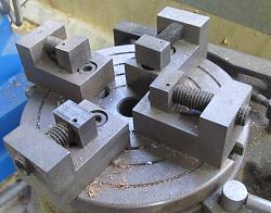
    My fence is just an afterthought; it works just as well as any more fancy machining could have given me.

  6. The Following 2 Users Say Thank You to CanBeDone For This Useful Post:

    Jon (Feb 14, 2020), rgsparber (Feb 15, 2020)

  7. #5
    Supporting Member rgsparber's Avatar
    Join Date
    Nov 2012
    Location
    Phoenix, AZ
    Posts
    1,324
    Thanks
    780
    Thanked 2,851 Times in 672 Posts

    rgsparber's Tools
    Quote Originally Posted by CanBeDone View Post
    There are two items I am missing in your design: It is not adjustable, and it doesn't have a fence.
    For a once-off job, being adjustable is, of course, not a issue. And if you are planning to bend several items, without a fence repeatability will be poor.
    This is what I learned after building this
    Click image for larger version. 

Name:	Bender.png 
Views:	297 
Size:	519.2 KB 
ID:	33533 following a suggestion found on this forum a few weeks ago, a three pin design very much like your own. Since I had to bend flat bar 6x32mm, instead of the pins I used pieces of 20mm plate, held in place by M10 bolts. The angle plate on the left is adjustable, and that is where my design failed: the three M10 bolts are not capable of holding the angle in place, and thus the bend is not as sharp and neat as I wanted it. Even though the high-tensile bolts have been tightened until the 20mm plate got (locally) deformed, the friction forces they do apply are not high enough, and slippage does occur - and thus the bend is no longer sharp.

    There is a solution, however, as exampled by tuomas Vise bending attachment: Instead of three pins use two vises, joined by a hinge. When closed loosely, these vises ought to give just the control over pin spacing that I need to give me the sharp bend that I want.
    For the vises, I will follow closely this design, used here on a rotating table: Click image for larger version. 

Name:	Vise.jpg 
Views:	264 
Size:	98.6 KB 
ID:	33534. Essentially, a M12 grubscrew has been grooved such that a 3mm roll pin connects it to the moving jaw, without blocking its ability to rotate freely.

    My fence is just an afterthought; it works just as well as any more fancy machining could have given me.
    CanBeDone,

    Thanks for sharing your experience! So far, I have been just playing around with the tool so had not considered problems related to repeatability. I have figured out the correct place to set the wire so the bend occurs where I want it so that is related to repeatability. If I understand your setup correctly involving two vises, I think it poses a problem for me. Say I want to bend this 7 gage wire every 1/4". I can see how the first bend would work with two vises but can't figure out how to do subsequent bends. Can you say more about how the two vises work?

    Thanks,

    Rick
    Rick

  8. #6
    Supporting Member rgsparber's Avatar
    Join Date
    Nov 2012
    Location
    Phoenix, AZ
    Posts
    1,324
    Thanks
    780
    Thanked 2,851 Times in 672 Posts

    rgsparber's Tools
    Quote Originally Posted by mbshop View Post
    First thing that came to mind while reading this was that both ends of the pins would have to be secured to prevent the pins from bending. Had to do this looooong ago. Forgot about it till you brought this up.
    Mbshop,

    Yup, the pins do bend a little but since the wire is near the base of each pin, it isn't bad enough to prevent good, sharp bends.

    Rick
    Rick

  9. #7
    CanBeDone's Avatar
    Join Date
    Oct 2019
    Posts
    43
    Thanks
    0
    Thanked 38 Times in 18 Posts
    Quote Originally Posted by rgsparber View Post
    CanBeDone,

    Thanks for sharing your experience! So far, I have been just playing around with the tool so had not considered problems related to repeatability. I have figured out the correct place to set the wire so the bend occurs where I want it so that is related to repeatability. If I understand your setup correctly involving two vises, I think it poses a problem for me. Say I want to bend this 7 gage wire every 1/4". I can see how the first bend would work with two vises but can't figure out how to do subsequent bends. Can you say more about how the two vises work?

    Thanks,

    Rick
    To give you a quick answer: No, my two-vise design won't work for bending distances that short. For such short distances I would use the techniques developed for bending chain links, such as


    or, to stay at home,
    Wire Bender
    Re-think on wire bender for making chain links

    My two-vise bender has been designed with just a single bend in mind, as this is all I need. Without too much effort, it can be re-designed for bends spaced at least 16mm (5/8") apart. That is the limit imposed by the M12 grub screw I use to move the movable jaw forward and backward. Changing that to something smaller would reduce permissible clamping stress to such a degree that I no longer would trust the vise not to break during use.
    If you look at any of the above links, all of them bypass the vise strength issue by bending around a former, custom made for the bending job on hand. This former replaces two of the three pins in a bender, which makes the whole device stronger and sturdier, allowing 180 degree bends, more than the 90 degrees you have contemplated in your design, and I have in mine. The dimensions of the third pin can be chosen for strength, they are not determined by desired bend spacing, as this pin will always be on the outside of the bend.

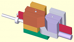
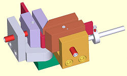
    To satisfy your curiosity regarding my tow-vise design, here it is
    Making Tight Bends with Heavy Gage Wire-bender-beforebending.png
    before bending and after making a 90 degree bend:
    Making Tight Bends with Heavy Gage Wire-bender-afterbending.png
    The green block is where the whole contraption is mounted in a bench vise, the gray and purple part is movable on a vertical axis, not visible here. The vertical axis was chosen so that the piece-to-be-bent can just be dropped into the contraption, without fastening any screws. The purple round bar on the right hand side of the first drawing accepts a 20mm (3/4") water pipe as a bending lever, not shown in the drawing. The part-to-be-bent is shown in red, resting against a silver fence on the left.

    My device so far does not have a fence to pre-set the bending angle, for that I still am looking for a good idea. Anybody out there with an idea that is truly rugged, as the bending forces I need to apply are substantial? (My 10 ton press cannot deliver the needed forces!)

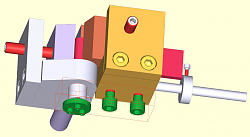
    Here is a look at the bending axis design, the green hinge-bearing block being outlined just as a wire frame.
    Making Tight Bends with Heavy Gage Wire-bender-hingedetail.png
    Three small screws hold a substantial washer against the 24mm diameter shaft of the hinge, so that there is no play. The shaft itself is press-fitted / glued into the movable (grey) vise.

    And here is a look at the internals of the moving jaw of the vise.
    Making Tight Bends with Heavy Gage Wire-bender-visedetail.png
    Downward forces are supplied by a T-nut (grey) and M4 screw, horizontal forces by a 3mm rolling pin resting inside a groove cut into the M12 grub screw. The pin is strong enough to withstand jaw opening forces, the 6mm diameter cylinder left after cutting the groove must sustain all the jaw closing forces, which means that the hole accepting the M12 grub screw needs to be flat-bottomed.

    I hope this helps

  10. The Following 2 Users Say Thank You to CanBeDone For This Useful Post:

    Beserkleyboy (Feb 18, 2020), Jon (Feb 17, 2020)

  11. #8
    Supporting Member rgsparber's Avatar
    Join Date
    Nov 2012
    Location
    Phoenix, AZ
    Posts
    1,324
    Thanks
    780
    Thanked 2,851 Times in 672 Posts

    rgsparber's Tools
    Superb explanation and renderings! Lots of food for thought.

    Thanks,

    Rick
    Rick

  12. #9
    Supporting Member Beserkleyboy's Avatar
    Join Date
    Aug 2014
    Location
    Sunny South Coast NSW, Australia
    Posts
    366
    Thanks
    473
    Thanked 230 Times in 134 Posts

    Beserkleyboy's Tools
    Great idea and presentation. What drawing program are you using? Thanks very much
    Jim

  13. #10
    Supporting Member rgsparber's Avatar
    Join Date
    Nov 2012
    Location
    Phoenix, AZ
    Posts
    1,324
    Thanks
    780
    Thanked 2,851 Times in 672 Posts

    rgsparber's Tools
    Quote Originally Posted by Beserkleyboy View Post
    Great idea and presentation. What drawing program are you using? Thanks very much
    Jim
    Jim,

    I use Alibre PE for 3D renderings and TurboCAD for 2D. It took me over 150 hours to master Alibre well enough for my needs. I also feed Alibre into CamBam to generate G-Code which then goes into Centroid software to control my CNC mill. Works well for me when machining 2 1/2 D.

    Rick
    Rick

Thread Information

Users Browsing this Thread

There are currently 1 users browsing this thread. (0 members and 1 guests)

Tags for this Thread

Bookmarks

Posting Permissions

  • You may not post new threads
  • You may not post replies
  • You may not post attachments
  • You may not edit your posts
  •