Free 186 More Best Homemade Tools eBook:  
Get tool plans

User Tag List

Page 1 of 4 1 2 3 4 LastLast
Results 1 to 10 of 33

Thread: Making tachometers and speedometers

  1. #1
    Supporting Member tonyfoale's Avatar
    Join Date
    Nov 2016
    Location
    Spain
    Posts
    1,609
    Thanks
    722
    Thanked 2,707 Times in 727 Posts

    tonyfoale's Tools

    Making tachometers and speedometers

    If you have some basic electronic skills it is easy to make your own speedo and/or tacho. All modern cars and bikes with analog instruments use tiny stepper motors to drive the needle and these are much more robust than the meter movements found in many after market offerings.

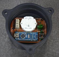
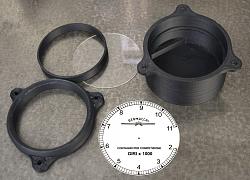
    I have just made a tacho for my race bike and I wanted something that looked like 1960/70s Italian race tacho. I got my son to 3D print the housing but that could easily be turned out of aluminium bar. I designed the dial in photopaint and printed it onto sticky backed label paper which I stuck to a thin aluminium backing disc, then I sprayed it with clear lacquer.

    To process the input pulses to drive the stepper motor I use an Arduino Nano, because of its small size. If you are interested I am quite happy to pass on full details and my software.

    Making tachometers and speedometers-dsc_5058.jpg Making tachometers and speedometers-tacho-bits.jpg

    Making tachometers and speedometers-tacho-innards.jpg

    186 More Best Homemade Tools eBook

  2. The Following 14 Users Say Thank You to tonyfoale For This Useful Post:

    Bummers (May 16, 2023), cellardweller (Jun 15, 2023), clavius (Jun 16, 2023), DIYSwede (May 17, 2023), fizzloid (Jun 15, 2023), freddo4 (Jun 14, 2023), hemmjo (May 16, 2023), Jon (May 16, 2023), lassab999 (May 16, 2023), mr mikey (Jun 15, 2023), nova_robotics (Jun 15, 2023), Ralphxyz (Jun 15, 2023), Saltfever (May 21, 2023), Sleykin (Jun 15, 2023)

  3. #2
    Supporting Member hemmjo's Avatar
    Join Date
    Feb 2017
    Posts
    2,665
    Thanks
    251
    Thanked 1,515 Times in 855 Posts

    hemmjo's Tools
    That would be nice for a tachometer for machine tool spindles also.

    2,000+ Tool Plans

  4. The Following User Says Thank You to hemmjo For This Useful Post:

    mr mikey (Jun 15, 2023)

  5. #3
    Supporting Member th62's Avatar
    Join Date
    Oct 2015
    Posts
    287
    Thanks
    0
    Thanked 512 Times in 172 Posts

    th62's Tools
    Definitely interested in the speedo details!
    I have messed around with steppers for my lathe's cross feed, unfortunately, the steppers were too small for that. they'd be far, far too big for a speedo, but small steppers are readily available, and cheap.
    i don't profess to know a lot about electronics, but I'm good with a soldering iron, I made a couple of digital voltmeters from kits many years ago and I have all the hardware for a hall effect ignition system, just haven't found a good schematic, or the time, to look at it.

  6. #4
    Supporting Member tonyfoale's Avatar
    Join Date
    Nov 2016
    Location
    Spain
    Posts
    1,609
    Thanks
    722
    Thanked 2,707 Times in 727 Posts

    tonyfoale's Tools
    Quote Originally Posted by th62 View Post
    Definitely interested in the speedo details!
    I have messed around with steppers for my lathe's cross feed, unfortunately, the steppers were too small for that. they'd be far, far too big for a speedo, but small steppers are readily available, and cheap.
    i don't profess to know a lot about electronics, but I'm good with a soldering iron, I made a couple of digital voltmeters from kits many years ago and I have all the hardware for a hall effect ignition system, just haven't found a good schematic, or the time, to look at it.
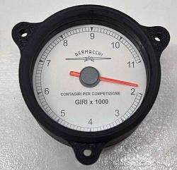
    I use a stepper motor "the white blob in the middle of the last photo" that is designed for the job and is used by several OEMs. They are readily available and they are surprisingly low cost. When I bought mine they came in a pack of three. I'll put together a PDF with full details and let you know. Fortunately it was only last week when I assembled the current one so it is reasonably fresh in my mind. I originally designed and built some about 10 years ago. The needles come with the motors and are an orange colour as in the first photo. This is from paint on the back side of the needle which can easily be scraped off and repainted with another colour so if you prefer black or white depending on your background colour it is easy to change. I just found a PDF file with data on the motor, with luck I have managed to attach it to this post. The motors have a movement range of 315 degrees but it is not necessary to use it all if it suits the look that you want with a smaller range on the dial. It is just a question of changing a number in my software.

    X27_168-InstrumentStepper.pdf

  7. The Following User Says Thank You to tonyfoale For This Useful Post:

    Saltfever (May 21, 2023)

  8. #5
    Supporting Member hemmjo's Avatar
    Join Date
    Feb 2017
    Posts
    2,665
    Thanks
    251
    Thanked 1,515 Times in 855 Posts

    hemmjo's Tools
    I will be keeping my eye on this for for more details. BUT, I will certainly understand if your other projects get in the way of you creating that PDF.

    The trouble with knowing how to do lots of different things and enjoying all of those different things is, there is never enough time to do all of them!!!

    As TH62 said, electronics it not my strong suit, but I can follow a schematic!!

  9. #6
    Supporting Member tonyfoale's Avatar
    Join Date
    Nov 2016
    Location
    Spain
    Posts
    1,609
    Thanks
    722
    Thanked 2,707 Times in 727 Posts

    tonyfoale's Tools
    Quote Originally Posted by hemmjo View Post
    I will be keeping my eye on this for for more details. BUT, I will certainly understand if your other projects get in the way of you creating that PDF.

    The trouble with knowing how to do lots of different things and enjoying all of those different things is, there is never enough time to do all of them!!!
    That is a problem that I know well. I am very bad at making records of what I do. e.g. Although it was around 10 years ago that I first made tachs in this manner it was not until last week that I had to trace through one to make a schematic. I find that it is useful for me to put in the effort, to make PDFs etc of projects, for other people because it gives me a permanent record also.

    Are either of you familiar with the Arduino?

  10. #7
    Supporting Member hemmjo's Avatar
    Join Date
    Feb 2017
    Posts
    2,665
    Thanks
    251
    Thanked 1,515 Times in 855 Posts

    hemmjo's Tools
    I have read a lot about Arduino and have plans to get started, but, time is the factor. In the past, 1980's, I built and programmed some devices to interface with early computers to run motors, record temperatures, and respond to other inputs.

  11. #8
    Supporting Member th62's Avatar
    Join Date
    Oct 2015
    Posts
    287
    Thanks
    0
    Thanked 512 Times in 172 Posts

    th62's Tools
    No, I've never used Arduino. I'm not interested in a tacho, just a speedo.

  12. #9
    Supporting Member tonyfoale's Avatar
    Join Date
    Nov 2016
    Location
    Spain
    Posts
    1,609
    Thanks
    722
    Thanked 2,707 Times in 727 Posts

    tonyfoale's Tools
    Quote Originally Posted by th62 View Post
    No, I've never used Arduino. I'm not interested in a tacho, just a speedo.
    Not a problem, but you will have to just follow instructions to load the software, it is quite easy. Speedo or tacho the hardware is the same it is just a matter of setting a number in the software to suit the number of pulses per sec that you will get from your wheel speed sensor.

  13. #10
    Supporting Member tonyfoale's Avatar
    Join Date
    Nov 2016
    Location
    Spain
    Posts
    1,609
    Thanks
    722
    Thanked 2,707 Times in 727 Posts

    tonyfoale's Tools
    Quote Originally Posted by th62 View Post
    ........ I've bought a magnetic sensor speedo so I don't have a great heavy cable running down beside the fork.
    I have just checked the schematic for my tacho and a speedo will be much easier to wire up. Most of the components in the tacho are for conditioning the noisy signals from the ignition system and you will not need that circuitry. A magnetic or optical wheel sensor will feed directly into the Arduino which feeds directly into the stepper.

    Please post a link to the speedo that you bought so that I can check out that the sensor is suitable. Also how do you plan on triggering the sensor? You may be able to do that off the bolts that hold the disc, unless they are non-magnetic stainless. You will get a smoother display with multiple pulses per wheel revolution. It is only a setting in the software to accommodate any number of pulses and the maximum speed that you want to display.

Thread Information

Users Browsing this Thread

There are currently 1 users browsing this thread. (0 members and 1 guests)

Bookmarks

Posting Permissions

  • You may not post new threads
  • You may not post replies
  • You may not post attachments
  • You may not edit your posts
  •