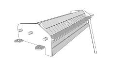
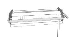
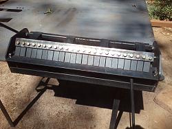
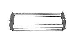
Here is the 3d model of a little swing brake I built. I will post some pictures of the actual unit tomorrow.
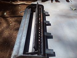
It is meant to be bolted to a table, and weighs 20-30 pounds, made from 1 1/2" angle iron, 1/4" plate, and some scraps of tubing. Each finger is 1" wide (made by cutting up a 1/2" x 1" bar and grinding to length by hand) and is held in by a 5/16" bolt. I will weld some of these in groups, just for convenience of alignment. This brake is capable of bending 2' of 16 gauge with a respectable radius. Also, no parts interfere with the metal, so you can push it all of the way through.
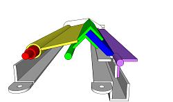
This picture shows construction and operation a bit better. The red section is a pipe welded offset to a rod to form a cam (in the actual build I ended up welding a nut in square tubing as the cam). When the cam rotates, it pushes the yellow assembly, which pushes the green tooling holder, forcing the blue fingers against the metal. A lever allows the operator to swing up the purple section to bend the metal.
If you want to change the fingers, release the red cam, and flip up the yellow assembly. This will allow you to flip up the green assembly, and access the teeth with ease.
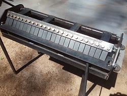
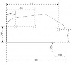
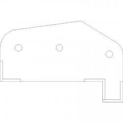
In the actual build, I ended up welding nuts to all parts, so that I can just bolt them into the frame, so all moving parts can be removed. It took two days in the school shop, at about three hours a day. It can be made with only a welder, an angle grinder, and a drill (I had access to a CNC plasma cutter, which is why the ends are that shape, but rectangular should be just fine. I drilled the holes in a drill press because plasma cutters don't make nice holes and I didn't want a sloppy machine)


 LinkBack URL
 About LinkBacks


 Reply With Quote



Bookmarks