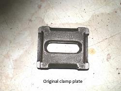
I got frustrated with using a spanner on the clamp bolt which never gripped that well, even over tightening made little improvement, upon studying the original cast clamp plate although a substantial casting it only had four small points of contact and a bolt head underneath which I thought was bending it under load.
I tried replacing the bolt with an Unbrako tee bolt only helped slightly. I thought should I throw more metal at the problem or try to design it out, I decided on the latter approach and at the same time convert to a lever clamp action.
There are many ways to do this and it largely depends on the tailstock you have to work with, to me the ideal result would be a cam supported at both sides of the clamp bolt to avoid any over stress of the pivot bearings as a lot of force is generated by a decent size clamp lever (which is what we want). I do not have a build log for this but I remember how I did it.
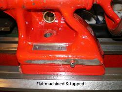
In my case I have a SB lathe with an open fronted tailstock with a fairly thin rear face to the casting so a front bearing is needed, all work is done in the lathe (its the only machine I have) so the first task is to machine a flat surface for a pedestal bearing on the front.
With the casting packed up on the cross slide and the barrel clocked square a flat surface is machined for this, (size is not important as the bearing mount is made to suit).
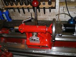
If you have an open frame casting such as [mr95gst] has on his SB you will need to do this front and back. Make your mount/s from alloy or steel and cap screw them to the machined surfaces then its back on the crosslide to bore or drill right though for the cam spindle directly over the hole through the base, no great precision for size needed as you will make the other parts to suit, some slight filing may be required on the though hole due to the angular movement of the eye bolt.
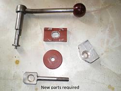
I have bronze bushed all pivot points and made the cam spindle from tool steel for long life with a cam portion offset of .062, just the eye bolt to make (3/8 inch x 18tpi) .
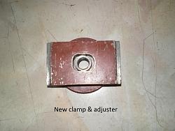
A new clamp plate from 1/2 inch m/s, and large knurled adjusting nut and whatever style of lever takes your fancy, you can see by the paint marks on the clamp plate the benefit of having a large clamp nut to minimize distortion.
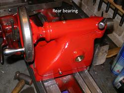
I have used a disc at the pedestal end of the shaft to add enough pressure to keep the lever in any position and to keep swarf out of the bearing. I used a bit of filler on the rear bearing to make it look as though its part of the casting.
This has been in use for many years now and is a great mod for lathes not so equipped, never had it move under load even using a 24 mm drill, finger pressure will do for most work and it makes backing out a drill for clearing so easy.
While the whole thing was apart I took the opportunity to graduate the hand wheel in 100 divisions and use a magnetic pointer for the rare occasions I need to use it.


 LinkBack URL
 About LinkBacks


 Reply With Quote


Bookmarks