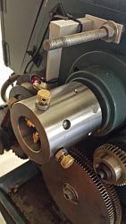
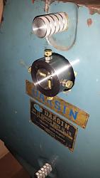
There are several different meanings to the term “Lathe Spider” published at HomemadeTools.net. The one I built is installed at the rear of the lathe spindle for a 12” swing X 37” gear head lathe and used to support longer rods held in the lathe chuck. The through hole in the spindle is 40 mm (1.575”).
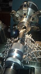
I have been machining the handles for various “kitchen” tools from small diameter 303 stainless steel rods and using the chuck spider at the rear of the metal lathe spindle helps to keep the small diameter rod from whipping-around (e.g., http://www.homemadetools.net/forum/k...ry-forks-66026 and http://www.homemadetools.net/forum/s...3072#post77395 ). This type of lathe spider chuck is also used in gunsmithing operations for rifle barrels.
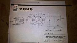
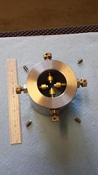
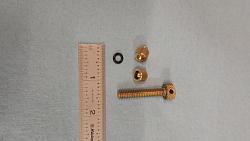
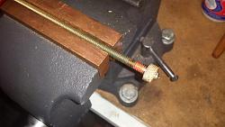
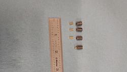
This lathe spider was machined from 3” dia. 1025 CRS using a left-over steel drop, a 0.5” dia. C360 free machining brass rod, and 0.5” hexagonal free machining 303 stainless steel, and using a section ¼-20 all-thread brass rod. Below are photos of my plans with the four spider knurled adjustment screw caps and ¼-20 all-thread brass rod used as "paperweights" , and the finished chuck spider, and followed by all the machining operations.
The first step was to machine the 3” dia. 1025 CRS drop to fit into the end of the lathe spindle and clear the 2.9” diameter opening in the lathe’s back cover for the change gears.
After test fitting the chuck spider for a less than 0.001” perfect sliding fit to the lathe spindle the next step was to make the brass adjustable holding screws and locking nuts. Rather than machining the adjustable holding screws from a solid C360 brass rod, I made the parts using ¼-20 all-thread brass rod and using a solid C360 brass rod made the knurled the 0.5” diameter adjustment heads with 0.125” cross-holes for doing adjusting.
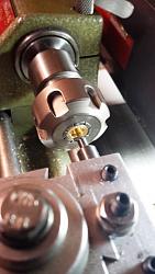
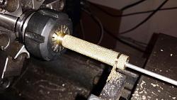
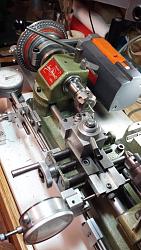
I also created special brass-ended caps with interior O-rings for the adjustment screws to support small (0.125”) diameter rods. This is the same technique I used for the Starrett V-blocks. (see page 2 to the posting http://www.homemadetools.net/forum/b...blocks-38166-2 ). The brass-ended caps were machined using a modified Unimat SL1000 lathe with a homemade ER16 collet chuck (see for the making of the ER 16 collet chuck http://www.homemadetools.net/forum/e...0273#post57039 ).
The knurled adjustment heads and all thread rods were joined with soft solder. The top of the knurled cap and side indent-details were machined to final dimensions after completing the soldering. This operation was actually much faster than totally machining from a C360 solid brass rod, wasting material, and single point threading the 1/4-20 adjustment screws. This saved a lot of the expensive C360 brass stock where super precision was not necessary.
The locking nuts were machined from 0.5” hexagonal 303 stainless steel rod and machined a 0.20” in width with internal ¼-20 threads (using a 1/4-20 tap while the part was still in the lathe chuck).
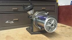
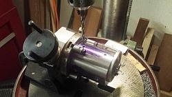
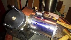
Next the layout and taping of the ¼-20 threads requiring precise locations were completed using a rotatory table indexed to one degree. The initial layout was completed on a granite plate and height gage. The layout provided guidance on where the holes should be in case I was off by one or two degrees but I relied on the rotatory table for the exact hole locations. The support of the spider chuck required creating special threaded rods and four short hollow rods for side support. Many times these types operations require making special tooling to make the tools and the special tooling can be used for other future work products. I used the Cogsdill Burraway 3/16 diameter tool to debur the outer edge and inner edge of the threaded holes after completing the threading.
Finally, the chuck spider must be attached to the lathe spindle using brass tipped set screws to prevent any damage to the lathe spindle. In addition I have Hall Effect Tachometer that uses a small magnet attached to the lathe spindle (see http://www.homemadetools.net/forum/1...6430#post22140 for how this works). This magnet is embedded in the chuck spider and held with Loctite 620.
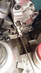
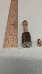
The picture below shows a simple fixture for holding stainless steel set screws for drilling end holes and was created from 1144 x 0.5” steel rod. The stainless steel set screws are not hardened and easier to drill. The cylinder is internally threaded with a ¼-20 thread and uses a ¼-20 cap screw from the opposite end to lock in the short stainless steel set screw for holding and drilling a 0.094” diameter hole. The hole is 0.125" deep and supports a 3/32" dia. x 0.250 long brass rod (shown below being machined in a highly modified Unimat SL1000 (see http://www.homemadetools.net/forum/m...00-lathe-10111). The Unimat ER16 collet is homemade and one of my best made accessories for this 3" swing small lathe ( http://www.homemadetools.net/forum/e...0273#post57039). The brass rod tips ensure a soft tip for holding the spider chuck onto the lathe spindle without any damage.
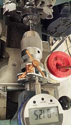
The photo below shows drilling ends of the stainless screws and the temporary setup for using a 1" depth mag-based digital dial indicator and a small Kant Twist clamp as a back-stop to measure the exact 0.125" depth of drilling.
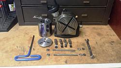
Below are the assembly of the brass tipped stainless steel set screws.
This was a fun project with lots of special parts.
Thank you for looking,
Paul


 LinkBack URL
 About LinkBacks



 Reply With Quote


Bookmarks