Free 186 More Best Homemade Tools eBook:  
Get 2,500+ tool plans, full site access, and more.

User Tag List

Results 1 to 3 of 3

Thread: INFO sought - Align 150 power feed for bridgeport milling machine

  1. #1
    Supporting Member desbromilow's Avatar
    Join Date
    Aug 2012
    Location
    Australia
    Posts
    811
    Thanks
    529
    Thanked 365 Times in 209 Posts

    desbromilow's Tools

    INFO sought - Align 150 power feed for bridgeport milling machine

    G'Day,

    I am in the slow process of restoring a Bridgeport 2J2 clone which has an align power feed fitted to the X axis.
    The switch/es which interact with the table stops are missing... I basically have some wires coming out of the powerfeed ending with the pulverised remains of a double sided switch.
    Does anyone have a wiring diagram for these type of power feeds, or know the configuration of the switch/es (normally open, normally closed, common return, etc?

    thanks,
    Des

    186 More Best Homemade Tools eBook

  2. #2
    Supporting Member metric_taper's Avatar
    Join Date
    Mar 2017
    Location
    Marion, Iowa
    Posts
    630
    Thanks
    244
    Thanked 272 Times in 165 Posts

    metric_taper's Tools
    I have this brand on my Wells-Index mill. On the Y axis and the knee (higher torque model).
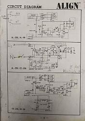
    I have the schematic that came with the install manual.
    The switches are single pole double throw. There are two of them, each one actuated by a left or right plunger that would be in the block, that is mounted to the saddle.

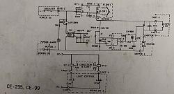
    The schematic in the manual is for 3 different models. The bottom one is for the European CE-235 model, that inhibits AC line power going to those limit switches, and I assume it is applicable to your system. This runs a low voltage DC out (13V zener shunt regulator per the schematic). Sorry for the quality of this schematic. The three wires as shown in the schematic are Limit-1, 2, 3. It looks like it powers a pair of relays, RY1, RY2, which switch the line voltage.
    If you open yours up, and see relays on the main circuit card, this is the right schematic. Other wise if it's like mine (USA delivery) the 2nd schematic is the one of interest. The top schematic is the Z axis knee schematic.
    INFO sought - Align 150 power feed for bridgeport milling machine-align-schematic-power-feed.jpgINFO sought - Align 150 power feed for bridgeport milling machine-align-schematic-power-feed-ce235.jpg

    Hopes this helps.

    2,500+ Tool Plans

  3. The Following 4 Users Say Thank You to metric_taper For This Useful Post:

    asterix (Apr 29, 2021), desbromilow (Apr 29, 2021), Sleykin (Apr 30, 2021), Toolmaker51 (Apr 28, 2021)

  4. #3
    Supporting Member metric_taper's Avatar
    Join Date
    Mar 2017
    Location
    Marion, Iowa
    Posts
    630
    Thanks
    244
    Thanked 272 Times in 165 Posts

    metric_taper's Tools
    Thinking about these schematics, they don't seem to be different between the CE version or US, from a component level to account for operation at 120VAC or 220VAC. Since this is manufactured in China, and they have a 220VAC power system, they may work better relative to speed setting. As this is one of my complaints, the range of speed on the control potentiometer is very narrow from slow to fast. Outside of that, I've been very happy putting this on the mill.

    Also it looks like to test your power feed out, you can just connect the 3 wires together on your cable, and it should run without issues, other then if it stalls out. That will test the circuit breaker.


    2,500+ Tool Plans

Thread Information

Users Browsing this Thread

There are currently 1 users browsing this thread. (0 members and 1 guests)

Bookmarks

Posting Permissions

  • You may not post new threads
  • You may not post replies
  • You may not post attachments
  • You may not edit your posts
  •