Free 186 More Best Homemade Tools eBook:  
Get tool plans

User Tag List

Page 1 of 2 1 2 LastLast
Results 1 to 10 of 14

Thread: HSM May/June 1988 - The Surface grinder (Part4)

  1. #1

    Join Date
    Oct 2017
    Posts
    9
    Thanks
    0
    Thanked 4 Times in 3 Posts

    carrdo's Tools

    HSM May/June 1988 - The Surface grinder (Part4)

    Has anyone made the retractable guide mount as described in the Home Shop Machinist "The Apprentice" The Surface Grinder, Part 4 by Robert Washbuurn in the May/June issue of the HSM?

    He describes there his own home shop fixture for holding the various dia. end mills using spring collets but I am trying to adapt a widely available and well known commercial unit which uses 5c collets. All of the commercial units, so far as I can tell, operate basically in the same way and all of them have the same limitations i.e. there is no positive built in tooth guide to position a tooth dead square to the grinding wheel itself if one is using a straight wheel in the surface grinder and if one wants to sharpen a center cutting end mill, one has to determine exactly where the center of the end mill is and and then position the edge of the grinding wheel exactly on this center.

    With all of the commercial fixtures, there is no provision to do either of the above operations except by eye and "by guess and by golly". I have destroyed more end mills this way than I care to admit and hence the reason for construction the retractable guide mount as described by Mr. Washburn (at least I hope that it will address these problems).

    So I am asking, has anyone made the unit and does it work as intended?

    The retractable guide mount is not a particular easy unit to construct as with anything related to end mill sharpening, both the geometry and the parts tolerances are exacting (i.e. is what you are producing dead square, dead parallel, truly straight and flat, concentric, positioned correctly and are the parts made to the specified tolerances, etc.etc.?). All of this has to be correct.

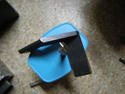
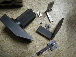
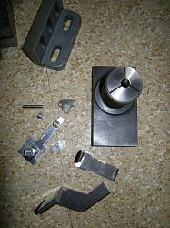
    I will include a photo of what has been produced here to date along with some notes on what not to do and things to be aware of when attempting to sharpen dull end mills. Please note that all of the above only relates to sharpening the end teeth on an end mill and has nothing to do with sharpening the spiral flutes which is another operation entirely involving completely different equipment.HSM May/June 1988 - The Surface grinder (Part4)-336-retractable-guide-mount-part-made-end-mill-holding-fixture-.jpg
    186 More Best Homemade Tools eBook
    Last edited by carrdo; Oct 31, 2017 at 02:44 PM. Reason: This thread is most suited to "Must Read" section but don't know how.

  2. #2

    Join Date
    Oct 2017
    Posts
    9
    Thanks
    0
    Thanked 4 Times in 3 Posts

    carrdo's Tools
    Some things one has to learn the hard way and I seem to be particularly prone to that. It's called the school of hard knocks.

    To start, if you want to sharpen the end of any smaller HSS end mill (say less than 1/2" dia.), using a surface grinder with a straight aluminum oxide vitrified bond wheel, then the wheel must have a sharp edge and not a rounded corner, so basically the wheel(s) one uses for end mill sharpening cannot be used for any other purpose. One needs to first true the wheel with a diamond on both the periphery of the wheel and on the side nearest you. For this you need a stout sliding bar (to hold the diamond) which allows it to slide vertically without shake. One only has to do this on the first 1/2" of the wheel or so. Just remove enough side material to produce the sharp edge.

    Secondly, truing and dressing a wheel are different operations entirely and have completely different purposes. Truing makes the wheel perfectly concentric to the spindle and aids in balancing the wheel. But truing with a diamond also dulls the grains of the wheel so it does not cut as freely and openly as it should (this results in generating heat also as the dull grains of the wheel do not shear the metal cleanly but rub to a greater extent). To dress an aluminum oxide vitrified wheel after truing it, one can use a commercial dressing stick (such as a Norbide or a coarse silicon carbide stick) which is lightly presented to the wheel by hand. The purpose of the dressing stick is to remove some of the vitrified bond to expose fresh cutting grains.

    Do I dress a grinding wheel after truing it? Not always even though I have all of the various dressing sticks for both diamond and aluminum oxide wheels. It takes a bit of "feel" and experience to dress a grinding wheel by hand and to do it properly and I do not want to advocate people sticking their bare hands around a 3600 RPM grinding wheel. As well, I don't have a brake type dresser (not in the budget) which professional commercial shops use.

    So why the sharp corner?

    It is not to have the wheel contact the next tooth of the cutter under any circumstances because if there is any contact with the wheel it will be on the cutting edge (lip) of the next tooth which will destroy the cutting edge. A rounded edge on the wheel means one has to move the wheel further and further towards the center of the cutter (and with smaller cutters there is not a lot of end relief or "gashing" on the cutter - more on this later) to permit this especially if one has to "eyeball" the position of the wheel in relation to "have I yet sharpened along the full length of the lip (the cutting edge) of the end mill". I have destroyed many, many cutters by going just a little bit too far and this applies even with a two lipped cutter whose cutting edges are spaced 180 degrees apart. One just can't see what is happening under the wheel.

    It gets more interesting but that is enough for now.

    2,000+ Tool Plans
    Last edited by carrdo; Oct 31, 2017 at 05:34 PM.

  3. The Following User Says Thank You to carrdo For This Useful Post:

    Toolmaker51 (Nov 2, 2017)

  4. #3

    Join Date
    Oct 2017
    Posts
    9
    Thanks
    0
    Thanked 4 Times in 3 Posts

    carrdo's Tools
    A basic question as to why one should have as sharp cutting tools as is possible to produce, specifically end mills in this case.

    I pride myself on being able to do precision machine work in a home shop environment.

    With a new commercially produced brand name end mill with the equipment I have, I can produce work that is square, parallel, flat and straight to +- 0.0005" over 3-4 inches having an excellent surface finish but with an end mill that has been used and still relatively sharp, I can only manage 0.002" - 0.003" over the same distance with a less than fine surface finish as the end mill will no longer make those very fine finishing cuts due to the slight dulling of the cutting edge which causes the cutter to start to ride over the surface of the work rather than cleanly shearing it.


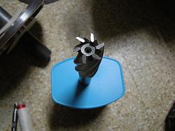
    Back to the topic at hand. What is end relief on an end mill? See the attached photo of an almost new 6 flute larger non center cutting end mill which has the end relief built in at the time of manufacture by the manufacturer. The end relief is the circular depression seen in the center of the end mill. It is the reason this type of end mill is called a non center cutting end mill as the cutting lips on the end mill do not extend all of the way to the center of the cutter. 99 % of the work I (we) do can use this type of end mill as it will mill a perfectly flat and straight surface. Center relief also makes it easier to sharpen the cutting lips on a surface grinder with the standard commercially available end mill sharpening fixtures and a straight grinding wheel when the cutter gets dull. But a some point, if we continue to sharpen the end of of the end mill, this center relief will disappear - then what?

    What a non center cutting end mill cannot do is plunge end mill unless we first driil a hole which is larger than the circular end relief built into the cutter (use this type of end mill to spot face for example or to counterbore. Actually, a dedicated and piloted spot facing or counterboring tool will do the job much better than an end mill but often the budget does not allow for this).

    Center cutting end mills have the cutting lips which extend all of the way to the center of the end mill and have no end relief. See the photo of a brand name nearly new two flute center cutting end mill. When new, they will plunge mill effectively. However, they are much more difficult to sharpen as one has to grind each cutting lip exactly to the center of the cutter and to be effective the cutting lips at the center have to meet as a fine line (for a two flute cutter) or as a point (with three or more flutes). Next to impossible to do in a home shop without having a dedicated tool and cutter grinder in good condition and having a ton of accessories.

    Next, we will delve into the cutting tooth geometry on an end mill which is really important.
    HSM May/June 1988 - The Surface grinder (Part4)-338-facet-geometry-new-two-flute-center-cutting-end-mill.jpg.HSM May/June 1988 - The Surface grinder (Part4)-337-end-relief-built-into-new-end-mill.jpg
    Last edited by carrdo; Nov 1, 2017 at 10:25 AM.

  5. The Following 2 Users Say Thank You to carrdo For This Useful Post:

    Jon (Nov 1, 2017), Toolmaker51 (Nov 2, 2017)

  6. #4
    Supporting Member Toolmaker51's Avatar
    Join Date
    Feb 2016
    Location
    Midwest USA
    Posts
    5,334
    Thanks
    7,044
    Thanked 3,012 Times in 1,901 Posts

    Toolmaker51's Tools
    Here is a related kink to form grinding, and squared wheels definitely apply. I keep small cards with my grinding equipment. Playing cards, the thinner versions of cardboard like cereal boxes, business cards (especially politicians, insurance or automotive salesmen) all work; thicker types for larger wheels. With the wheel spinning, 'burn' the card edge lightly into the wheel corner you wish to examine. It will replicate the form quite well. It can be magnified with a glass, viewed on a comparator, or projected on a dark wall with a bright incandescent lamp. If scale isn't particularly important, judging results of tangents etc is pretty easy. If you produce a scaled up drawing, and project the shadow on it, a higher degree of precision is possible, just manipulate the focal distance.
    I have an old Army Signal Corps opaque projector for that very process. Also works for laying out sketches to full size, with decent results. Transparent [overhead] projectors are easier to find.
    Sincerely,
    Toolmaker51
    ...we'll learn more by wandering than searching...

  7. #5

    Join Date
    Oct 2017
    Posts
    9
    Thanks
    0
    Thanked 4 Times in 3 Posts

    carrdo's Tools
    If you want to see on Youtube the process I am going to describe in more detail, see: How to Sharpen End Mills on a Surface Grinder Part 1 with Dale Derry.

    After sharpening his two flute end mill (as I shall describe how to do it his way also and with a variation on it), he puts the previously dull end mill to use and then breaks it showing the limitation of what end sharpening will do for you in that if you only sharpen the end teeth on an end mill and not the spiral flute teeth (if they are dull also), one is limited to making shallow surfacing cuts (which is OK by me as it just involves using up more of one's time but since I am retired...) and as well there is an increased danger of chipping a corner if you really go at it but with the speeds and feeds I employ not likely. I look for a good surface finish and can I produce square and parallel surfaces...

    The sharpening of the spiral teeth on an end mill is a whole other process and there are limitations here also besides reducing the diameter of the end mill (I love undersize end mills and use them all the time), but with repeated sharpening one changes (reduces) the cutting teeth positive rake angle and if it is in the form of a hook profile also and most HSS end mills have this feature (as the hook promotes free cutting and a fine surface finish while a positive tooth rake angle reduces end mill deflection and has a lower power requirement vs a neutral or negative rake cutting edge). And when the positive tooth rake angle is compromised, the performance of the end mill is seriously degraded but I digress... So there are limitations whatever you do.

    I will make up a sketch to illustrate the above but I am no great artist.

  8. #6
    Supporting Member Ralphxyz's Avatar
    Join Date
    Dec 2016
    Posts
    1,733
    Thanks
    3,229
    Thanked 295 Times in 241 Posts

    Ralphxyz's Tools
    Thanks carrdo!!

    Ralph

  9. #7

    Join Date
    Oct 2017
    Posts
    9
    Thanks
    0
    Thanked 4 Times in 3 Posts

    carrdo's Tools
    To continue, take a new two flute end mill and examine a cutting tooth on the end of the end mill specifically the cutting edge corner of the end mill with an eye loupe under good lighting. You will notice that the outermost part of the cutting edge is likely straight followed closely by a shallow scallop or hollow ground section. This scallop or hollow ground section is called "the hook" and forms part of the cutting edge "rake".

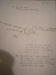
    Rake is very important in an end mill. Now, take a look at my non professional photos of my non professional sketches (I did directly scan my sketches but the scan format was not recognized so I had to take some not so good photos of the sketches made).

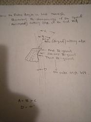
    What is rake? See the first sketch (for some reason they came out reversed - the last photo is the first). It is a blown up sketch of a cross section of the cutting edge of a tooth of the end mill. Rake is the angle the tip of the cutting edge makes with a radial (imaginary) line drawn through the center of the end mill. Radial means radiating out from the center like the spokes on a bicycle tire. As sketched, the rake is positive as found on HSS end mills.

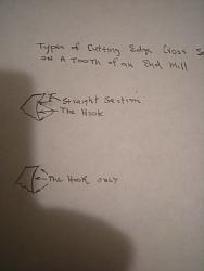
    See the second sketch. There are generally two types of cutting edge cross sections which can be found on positive rake HSS end mills. Type "A" is a composite (found on the vast majority of HSS end mills) in that it has a straight section followed by the hook. Type "B" is a true hook cutting edge. Why the difference and what are the advantages and disadvantages of each type of cutting edge profile?

    The type "A" cutting edge profile allows for the resharpening of an end mill without compromising the rake angle until repeated sharpening of the cutting edge "uses up" the straight section of the cutting edge and we move into the hook section. See the third sketch for what happens after repeated re-sharpenings of a Type "A" cutting edge end mill and how the rake sooner or later becomes compromised.

    The type "B" or a true hook cutting edge profile gives a free cutting and a fine surface finish but it is prone to dulling or edge breakdown as, due to its shape, the tip of the cutting edge is weaker as there is less metal backing up the cutting edge. Think of a bird of prey, both its curved beak and talons are a more extreme example of the efficiency of a hook cutting edge for slicing and slashing. Metal (steel) is much more difficult to slice than flesh so we have to modify the hook cutting edge on an end mill somewhat but the principle is the same - a hook is a very efficient cutting edge/profile.

    End mill manufacturers have to take many conflicting factors into account such as the cost and ease of manufacture, the life of the cutter, the ease of sharpening, the use (and abuse) to which the cutter will be put, the type of metal (or the many types of metal it will encounter) etc. etc. The type "A"cutting edge profile represents a practical compromise especially when the many different types of the more common materials such as are found in a home workshop need to be worked. A HSS end mill is certainly not the cutter of choice when very difficult or more exotic materials come into the picture.

    Even with all of the above, we have just barely scratched the surface. Stay tuned.

    If something is not clear, just ask. If I don't know, I will say so and somebody else can jump in.

    PHSM May/June 1988 - The Surface grinder (Part4)-346.jpgHSM May/June 1988 - The Surface grinder (Part4)-345.jpgHSM May/June 1988 - The Surface grinder (Part4)-344.jpg
    Last edited by carrdo; Nov 3, 2017 at 07:46 PM.

  10. #8

    Join Date
    Oct 2017
    Posts
    9
    Thanks
    0
    Thanked 4 Times in 3 Posts

    carrdo's Tools
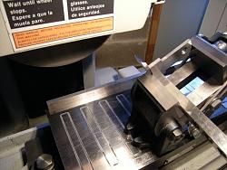
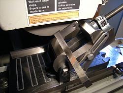
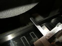
    As this site is all about homemade tools, I guess I should show some photos of the progress being made on the Washburn retractable guide mount. I am living on coffee and nerves as this project is starting to feel like a pyrrhic victory.

    Back to my tome.

    So what can be considered a minimum size an end mill can be reground to (on its diameter) before it really can't be sharpened any further?

    I am very fortunate to have a copy of the DoAll "End Milling Handbook" which includes a table showing this. For the sizes we normally encounter, they give the following: 1/8" (0.110"), 1/4" (0.210"), 3/8" (0.320"), 1/2"(0.425"), 5/8" (0.530"), 3/4" (0.635"), 1" (0.850") and for many other sizes as well. This is for a composite Type "A" cutting edge end mill tooth profile - all credit going to DoAll.

    There are literally boxes full of used end mills here which will outlast me as one can make bulk purchases of used end mils at very reasonable prices (less than $1 per piece) if one is prepared to hunt on places like Kijiji, Craigslist, ebay, etc. and be patient until the right deal comes along. So now with the above information and a micrometer, one can easily check the useful life left in any particular endmill. In industry, since time is money, and since the advent of carbide and the more exotic coated inserts, no one these days is taking the time (or keeps the equipment) to re-sharpen a HSS end mill so local machine shops are good places to look and make a deal as well since used HSS end mills are just thrown away.

    On my end mill grinding fixture, which is the well known American make, they quote the same relief angles as stated by Dale Derry for his offshore brand namely 5 degrees primary end relief, 30 degrees secondary end relief and 2 degrees center relief. I do have the instructions which come with this unit but they are very basic. They also make a fixture for 10 flute shell end mill cutters which is virtually identical to the one made for regular end mills.

    As Dale states, the relief angles built into all of these fixtures are very generic and don't always represent the ideal clearance angles for the range of end mill sizes which we use (typically 1/8" to 3/4"). For example, the commercial T&C grinding shop where I used to take all of my cutters for sharpening before they closed down, said to use 15 degree secondary end relief for the general type of work I do instead of 30 degrees as it leaves more metal behind the cutting edge which makes it stronger and I never encountered a problem having end mills with this smaller secondary relief.

    Having said that, the DoALL End Mill Handbook quotes vastly different relief angles (with the general rule being, the smaller the diameter of the cutting tool, the greater is the relief - it is exactly the same for drills, single point lathe tools cutting small diameter work, etc.). To quote some examples from the DoALL Handbook:

    1/8" - 16 degree primary relief and 28 degree secondary relief
    1/4" - 12 degree primary relief and 21 degree secondary relief
    3/8" - 11 degree primary relief and 19 degree secondary relief
    1/2" - 10 degree " " and 18 degree " "
    3/4" - 9 " " " and 17 " " "

    Many other sizes are also included in the table with all credit going to DoALL.

    So as you can see from the above, these grinding fixtures give results which are not ideal at all but at the speeds and feeds which we run our cutters at vs industry, they will do the job.

    In addition, the cutting edge land width, when one grinds the primary relief angle is very important and is much narrower than one would think.

    Again, from the DoALL Handbook:

    1/8" - 0.005"-0.007" land width
    1/4" - 0.007"-0.009" " "
    3/8" - 0.009"-0.012" " "
    1/2" - 0.012"-0.016" " "
    3/4" - 0.016"-0.020" " "

    Many other sizes are also given in the table with all credit going to DoALL.


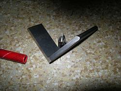
    HSM May/June 1988 - The Surface grinder (Part4)-347-setup-grind-lip-gauge-piece.jpgHSM May/June 1988 - The Surface grinder (Part4)-348-will-clear-.jpgHSM May/June 1988 - The Surface grinder (Part4)-349-after-grinding.jpgHSM May/June 1988 - The Surface grinder (Part4)-350-getting-closer.jpg
    Last edited by carrdo; Nov 4, 2017 at 05:59 PM.

  11. The Following User Says Thank You to carrdo For This Useful Post:

    Jon (Nov 4, 2017)

  12. #9

    Join Date
    Oct 2017
    Posts
    9
    Thanks
    0
    Thanked 4 Times in 3 Posts

    carrdo's Tools
    Moving right along.

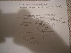
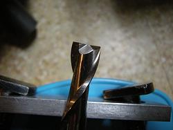
    Take a look at the included photo of the like new two flute center cutting end mill from a different angle which clearly shows the tooth face facet or what I call the third facet. You can see that the facet makes a square a corner cut from the center of the end mill but the grinding just misses the cutting edge of the tooth where it is scalloped and beyond to the cutting edge corner of the end mill.

    So why the third facet? Maybe the answer is obvious to all of you but just so that no stone is left unturned, one needs the third facet in this type of end mill as one has to remove all of the metal in front of the end mill teeth cutting edges so they are left clear to cut. At some point then, when sharpening the end of a two lipped end mill, one will also have to grind back the third facet in addition to the primary and secondary clearance facets on the cutting edges themselves.

    With a 90 degree corner on a straight wheel, the end mill cannot be indexed 90 degrees after grinding the primary and secondary clearance facets or it will also grind the opposite tooth cutting edge so it has to be indexed at something less than 90 degrees. I also use 88 degrees as the preferred angle to grind the third facet as per Dale's video but here is the problem. All of these end mill sharpening fixtures index 24 divisions and 24 divisions only (every 15 degrees) so one cannot have the desired 3rd facet indexing without resorting to some additional tricks. I also use a 2 degree angle piece but in my case I do not angle the end mill itself - I angle the entire fixture. I do it this way because the fixture which I have seems to need three hands to hold, position and then tighten the draw in cap which locks the 5C collet down into the body of the fixture. Included is another hand sketch showing all of the above.

    In order to work properly, the fixture must index positively. I found on mime that some indexing positions were definitely very "mushy" until it was discovered that the draw in in cap which draws the 5C collet down into the body of the fixture was running slightly eccentric on the collet threads and binding against body of the fixture. Slightly turning down the OD of the cap relieved the problem. It may not have been the fault of the fixture as the threads on the collet could have been mis-manufactured but I had the same problem with all of the collets. Just something to be aware of, the fixture has to index both freely and positively as one has to count the number of "clicks" as one is indexing and even then it is very easy to go one click too much or one click too few because you are doing it dozens of times.

    Solving the above problems still leaves the problem of determining where the exact center of the end mill is and that is where my modified method comes in.

    I noticed that Dale was using what looked to be a diamond wheel in his video. A straight diamond wheel comes with a square corner as manufactured and one does not have to true a diamond wheel as it should run dead true on the SG spindle as manufactured. Still, a resinoid diamond wheel needs to be dressed from time to time, an operation which was new to me until recently. (I don't know about plated or other types of diamond wheels).

    Magnification will also help locate center. I use magnification also but there is magnification and then there is true optics. My friend sharpens all of his end mills by hand and they cut but he has a vey fancy binocular microscope having a large depth of field, built in illumination, a variety of engraved line (?) reticules and a million and one other desirable features (I don't know optics so I can't say what the most desirable features are). Only problem is, you would pass out at the cost.

    HSM May/June 1988 - The Surface grinder (Part4)-353-sketch-setup-grinding-tooth-face-facet-third-facet-square-corner-str.jpg


    HSM May/June 1988 - The Surface grinder (Part4)-339-third-facet-new-two-flute-center-cutting-end-mill.jpg
    Last edited by carrdo; Nov 5, 2017 at 08:31 PM.

  13. #10

    Join Date
    Oct 2017
    Posts
    9
    Thanks
    0
    Thanked 4 Times in 3 Posts

    carrdo's Tools
    If finding the exact center on a two flute end mill on the surface grinder is that difficult, is it possible to do without the center at all? Yes I believe it is. I call it the gashing operation.

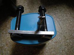
    The gashing operation in its simplest form on a two flute end mill is the creation of a narrow transverse slot which removes all of the center material. See the attached photos of an end mill which has been gashed this way. Gashing an end mill allows one to advance the grinding wheel up to to and past center of the end mill without touching or harming the opposite tooth lip or cutting edge. The gashing operation itself is done with a narrow cutoff wheel.

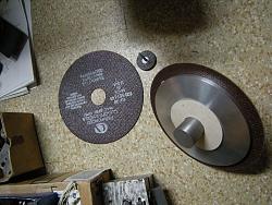
    For the smallest end mills less than 1/4" diameter, I employ the little Dremel type cut off wheel shown in the photo. For end mills 1/4"-3/4" diameter, I use the reinforced commercially available 7" dia. cutoff wheels which are only 0.035" thick. For the larger wheels, I custom made the large diameter relieved aluminum washers which go on each side of the wheel so that only about 1/2" depth of the wheel is exposed.

    To make the gash, the cutoff wheel is positioned so that one edge of the cutoff wheel is positioned approximately over the center of the end mill by eye or by using a graduated scale with a stop as an aid and then the cutoff wheel is fed down in 0.005" depth increments while making a traverse pass with the table of the surface grinder. Use coolant with this operation. Only go as deep (0.020"-0.040") as is necessary to relieve the center of the end mill as you do not want to weaken the cutting end by making a deep cut. The end mill holding fixture is advanced three clicks so that the end mill flutes are set at a 45 degree angle to the cutoff wheel or one can go straight across with the end mill flutes set at 90 degrees.

    One still has to take care when grinding the primary land and secondary clearance angles on the end mill as the slots produced are very narrow.

    I just learned that two flute end mills are produced commercially to be center cutting so one must be aware that gashing an end mill this way makes it non center cutting.

    How does the above work? The proof of the pudding is in the eating as the expression goes. I will conclude next time showing an actual milling operation with this type of end mill and what the results are.

    HSM May/June 1988 - The Surface grinder (Part4)-340-gashing-used-now-non-center-cutting-two-flute-end-mill.jpgHSM May/June 1988 - The Surface grinder (Part4)-341-another-photo-gashing-different-angle.jpgHSM May/June 1988 - The Surface grinder (Part4)-342-very-thin-reinforced-resinold-bond-cutoff-wheels-used-end-mill-gashing.jpg
    Last edited by carrdo; Nov 25, 2017 at 12:05 AM.

Thread Information

Users Browsing this Thread

There are currently 1 users browsing this thread. (0 members and 1 guests)

Bookmarks

Posting Permissions

  • You may not post new threads
  • You may not post replies
  • You may not post attachments
  • You may not edit your posts
  •