Free 186 More Best Homemade Tools eBook:  
Get 2,500+ tool plans, full site access, and more.

User Tag List

Results 1 to 9 of 9

Thread: How to turn ogives

  1. #1
    Supporting Member mklotz's Avatar
    Join Date
    Aug 2015
    Location
    LA, CA, USA
    Posts
    3,550
    Thanks
    363
    Thanked 6,586 Times in 2,166 Posts

    mklotz's Tools

    How to turn ogives

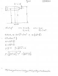
    An ogive is the shape formed by the pointed Gothic style arches. It is formed by the intersection of two circular arcs such that a sharp point is formed at the point of intersection. Of more application to metalworkers, 'ogive' is also used to describe the three dimensional shape typical of a rocket nose cone. Its cross-section has the same mathematical description as the Gothic arch.

    Ogives can be turned incrementally on a lathe by first developing a table of (x,y) values that define the shape, then making a series of plunge cuts based on those values. A final finish is then done with a file and emery paper.

    The attached diagram shows the math to develop the (x,y) value pairs as a function of the parameters of the desired ogive. Tedious work at best; that's why I wrote a program (OGIVE.C) to do this. An input data file is used to specify the ogive parameters and the details of the 'x' step size and tool width then, when the program runs it produces a cutting schedule that can be carried to the lathe to guide the turning.
    How to turn ogives-ogive.jpg

    186 More Best Homemade Tools eBook
    ---
    Regards, Marv

    Failure is just success in progress
    That looks about right - Mediocrates

  2. The Following 4 Users Say Thank You to mklotz For This Useful Post:

    Bony (Apr 20, 2021), NailByte (Apr 21, 2021), NortonDommi (Apr 12, 2021), Toolmaker51 (Apr 13, 2021)

  3. #2
    Content Editor
    Supporting Member
    DIYer's Avatar
    Join Date
    Aug 2013
    Posts
    3,055
    Thanks
    798
    Thanked 1,897 Times in 1,692 Posts


    Thanks mklotz! We've added your Ogive Turning Calculator to our Machining category,
    as well as to your builder page: mklotz's Homemade Tools. Your receipt:


    2,500+ Tool Plans
    New plans added on 01/15/2025: Click here for 2,702 plans for homemade tools.

  4. #3
    Supporting Member rgsparber's Avatar
    Join Date
    Nov 2012
    Location
    Phoenix, AZ
    Posts
    1,328
    Thanks
    781
    Thanked 2,859 Times in 674 Posts

    rgsparber's Tools
    Quote Originally Posted by mklotz View Post
    An ogive is the shape formed by the pointed Gothic style arches. It is formed by the intersection of two circular arcs such that a sharp point is formed at the point of intersection. Of more application to metalworkers, 'ogive' is also used to describe the three dimensional shape typical of a rocket nose cone. Its cross-section has the same mathematical description as the Gothic arch.

    Ogives can be turned incrementally on a lathe by first developing a table of (x,y) values that define the shape, then making a series of plunge cuts based on those values. A final finish is then done with a file and emery paper.

    The attached diagram shows the math to develop the (x,y) value pairs as a function of the parameters of the desired ogive. Tedious work at best; that's why I wrote a program (OGIVE.C) to do this. An input data file is used to specify the ogive parameters and the details of the 'x' step size and tool width then, when the program runs it produces a cutting schedule that can be carried to the lathe to guide the turning.

    Click image for larger version. 

Name:	OGIVE.jpg 
Views:	448 
Size:	97.1 KB 
ID:	39217
    Ah yes, Manual Numeric Control. As I understand it, the technique was first used to make helicopter blades near the end of WWII. Guy Lautard's Bedside Reader has a great article on this. I translated his approach into a pocket calculator but, for the general case, I think a spreadsheet works better.

    Rick
    Rick

  5. #4
    Supporting Member mklotz's Avatar
    Join Date
    Aug 2015
    Location
    LA, CA, USA
    Posts
    3,550
    Thanks
    363
    Thanked 6,586 Times in 2,166 Posts

    mklotz's Tools
    Quote Originally Posted by rgsparber View Post
    Ah yes, Manual Numeric Control. As I understand it, the technique was first used to make helicopter blades near the end of WWII. Guy Lautard's Bedside Reader has a great article on this. I translated his approach into a pocket calculator but, for the general case, I think a spreadsheet works better.

    Rick
    I prefer to call it HAM - Human Assisted Machining - the flip side of CAM.
    ---
    Regards, Marv

    Failure is just success in progress
    That looks about right - Mediocrates

  6. #5
    Supporting Member rgsparber's Avatar
    Join Date
    Nov 2012
    Location
    Phoenix, AZ
    Posts
    1,328
    Thanks
    781
    Thanked 2,859 Times in 674 Posts

    rgsparber's Tools
    Quote Originally Posted by mklotz View Post
    I prefer to call it HAM - Human Assisted Machining - the flip side of CAM.
    Doesn't sound too Kosher to me ;-)

    Rick
    Rick

  7. #6
    Supporting Member Toolmaker51's Avatar
    Join Date
    Feb 2016
    Location
    Midwest USA
    Posts
    5,338
    Thanks
    7,048
    Thanked 3,020 Times in 1,905 Posts

    Toolmaker51's Tools
    Extracted salient point of Marv's present(tation).
    attached diagram shows the math to develop the (x,y) value pairs as a function of the parameters of the desired ogive. Tedious work at best; that's why I wrote a program (OGIVE.C) to do this.
    So, for the rest of us, adversity factor is...?

    Far as acronyms go, Manual Numerical Control is good, Human Assisted Machining is too; how about MCC?
    Manual Coordinate Control?
    Last edited by Toolmaker51; Apr 13, 2021 at 07:48 PM.
    Sincerely,
    Toolmaker51
    ...we'll learn more by wandering than searching...

  8. #7
    Supporting Member Bony's Avatar
    Join Date
    May 2015
    Location
    Tasmania, Australia
    Posts
    392
    Thanks
    64
    Thanked 187 Times in 67 Posts

    Bony's Tools
    Does anyone know if the ogive cross section shape has any special characteristics, like a shape for minimal drag.
    I'm helping a mate build an aircraft (full size Mk 1 Spitfire) and it would be useful to know for machining things like pitot tube fairings etc.

  9. #8
    Supporting Member NortonDommi's Avatar
    Join Date
    Jul 2014
    Location
    North Island, New Zealand.
    Posts
    990
    Thanks
    1,800
    Thanked 533 Times in 319 Posts

    NortonDommi's Tools
    Somewhere in the depths one of the books I have on fluid dynamics has 1/2 a chapter on the Ogive shape as it pertains to airships,(blimps with engines). From memory much depends on speed and within certain boundaries the shape has minimal drag. Been a good 10 years since I saw it though otherwise I'd copy the relevant pages for you.
    I am sure someone with more in depth knowledge will have the answer.

  10. #9
    Supporting Member mklotz's Avatar
    Join Date
    Aug 2015
    Location
    LA, CA, USA
    Posts
    3,550
    Thanks
    363
    Thanked 6,586 Times in 2,166 Posts

    mklotz's Tools
    Quote Originally Posted by Bony View Post
    Does anyone know if the ogive cross section shape has any special characteristics, like a shape for minimal drag.
    I'm helping a mate build an aircraft (full size Mk 1 Spitfire) and it would be useful to know for machining things like pitot tube fairings etc.
    There's an excellent Wikipedia article which discusses the various shapes and their drag characteristics in different speed domains...

    https://en.wikipedia.org/wiki/Nose_c...haracteristics


    2,500+ Tool Plans
    ---
    Regards, Marv

    Failure is just success in progress
    That looks about right - Mediocrates

Thread Information

Users Browsing this Thread

There are currently 1 users browsing this thread. (0 members and 1 guests)

Bookmarks

Posting Permissions

  • You may not post new threads
  • You may not post replies
  • You may not post attachments
  • You may not edit your posts
  •