Free 186 More Best Homemade Tools eBook:  
Get tool plans

User Tag List

Page 1 of 2 1 2 LastLast
Results 1 to 10 of 14

Thread: How to make a 6000rpm Bridgeport.

  1. #1
    Supporting Member tonyfoale's Avatar
    Join Date
    Nov 2016
    Location
    Spain
    Posts
    1,607
    Thanks
    721
    Thanked 2,706 Times in 726 Posts

    tonyfoale's Tools

    How to make a 6000rpm Bridgeport.

    Requirement and motivation.

    I have a Bridgeport mill which I bought when I lived in the US for a while. The maximum speed shown on the adjusting dial is 4200 rpm but the electricity supply in the US is 60Hz and back here in Spain it is 50Hz so instead of a maximum speed of 4200, all I could hope for would be 3500rpm. Most of my work is with Aluminium with relatively small cutters and 3500rpm is way short of optimum. In addition as the speed of the machine rose above about 2500rpm it rattled and vibrated badly, so I did not like to run it at maximum.
    I decided to dismantle the head to investigate the rattle and to evaluate the feasibility of upping the maximum rpm. I have ended up with a 6000rpm machine with a 5hp motor in place of the original 1.5hp and 3500rpm. The speed is controlled by a VFD (Variable Frequency Drive) in place of variable pulleys and it runs dead smooth and quiet.

    How to make a 6000rpm Bridgeport.-bridgeport_01.jpg Click thumbnails for full size.

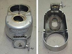
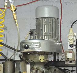
    Above are the before and after pictures. Note that the height of the top of the cover has been drastically lowered. The LH image shows the original speed adjuster.

    How it was done.
    How to make a 6000rpm Bridgeport.-bridgeport_05.jpg How to make a 6000rpm Bridgeport.-bridgeport_06.jpg

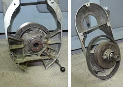
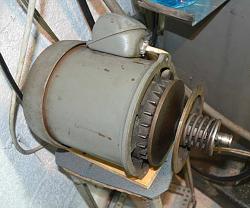
    Here we can see the original variable pulley speed variation mechanism. The motor pulley is spring loaded to allow it to adjust the spacing and hence effective diameter. The driven pulley, which sits directly above the spindle, has its spacing controlled by a lever, which in turn is moved by a chain which is pulled by a worm gear system attached to the adjustment handle. This mechanism is shown in the following images.

    How to make a 6000rpm Bridgeport.-bridgeport_02.jpg

    How to make a 6000rpm Bridgeport.-bridgeport_08.jpg

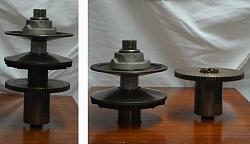
    The above shows more detail of the drive mechanism to the spindle. The piece to the far right is used but the rest is not in the new drive system.
    How to make a 6000rpm Bridgeport.-bridgeport_03.jpg How to make a 6000rpm Bridgeport.-bridgeport_04.jpg

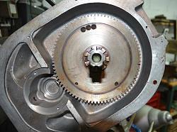
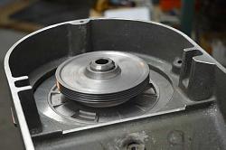
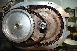
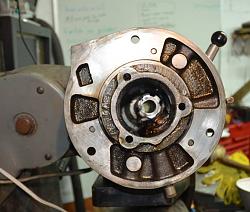
    With the removal of the main drive pulleys we are left with a view down onto the back gears mechanism, a combination of a gear pair and toothed belt and pulleys. The original intent was to retain the back gears in order to retain the torque multiplication at low speeds but then I realized that I had never had need to use them in the past and decided to go for simplicity. The image to the right shows the cleaned housing (which is no longer required) and the only part of the original drive that will be used. A loose engagement of the face drive dogs, which can be seen near the centre, was responsible for the rattle and rough running at high speeds. I did consider removing the bulk of the gear but decided to leave it to gain some inertia. The teeth on the gear have proved useful for two other features and I am very glad to have retained the gear. I used the teeth to trigger a magnetic sensor for speed measurement and control. The teeth are also used as part of a holding brake, as we'll see later.
    How to make a 6000rpm Bridgeport.-bridgeport_07.jpg How to make a 6000rpm Bridgeport.-bridgeport_09.jpg

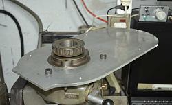
    With the two housings, one for the back gears and the other for the main drive pulleys no longer in use, we are left with the mounting surface shown above to the left. on the right we see a mounting plate to replace the removed housings and provide a base for the top cover which supports the motor.
    How to make a 6000rpm Bridgeport.-bridgeport_10.jpg How to make a 6000rpm Bridgeport.-bridgeport_12.jpg

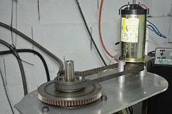
    Initially I fitted a 2hp DC motor from an exercise treadmill, there was a two fold purpose for this. Firstly I needed to be able to run the mill to do some machining for the conversion, and secondly I was hopeful that it would be man enough to be a permanent solution, but that was regarded as a test. The LH picture shows the motor mounted in temporary fashion to provide the machining capability. The other shows the top cover in place and it is obvious that it is too tall to put a motor support plate on it. So the first task was to machine the top cover down to the correct height.
    How to make a 6000rpm Bridgeport.-bridgeport_13.jpg How to make a 6000rpm Bridgeport.-bridgeport_14.jpg

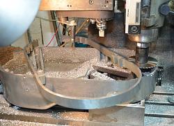
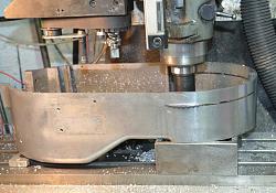
    I used a slitting saw to cut the required amount from the top cover as shown above. This was the first test of the DC motor and it worked pretty well with the large diameter slitting saw.
    ** Encouraging**
    However, I then spotted on a well known auction site a brand new 5hp 3ph motor for 50 euros (it turned out that the seller had entered the wrong price), it was a no-brainer and I bought it immediately.

    How to make a 6000rpm Bridgeport.-bridgeport_15.jpg

    Above we have the underside view of the new motor fitted to the top cover. I am a big fan of the poly-V belt, they have plenty of torque capacity in a small size and bend around pulleys with a minimum of effort leading to a very smooth drive. I made the poly-V pulleys from some gears that I had saved from an old lathe.
    How to make a 6000rpm Bridgeport.-bridgeport_16.jpg How to make a 6000rpm Bridgeport.-bridgeport_17.jpg

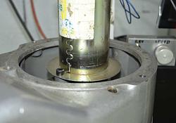
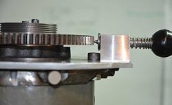
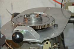
    Here is the driven pulley directly above the main spindle, the spring loaded thingie is a manually operated spindle lock to hold it solid when installing and removing cutters. One of the two uses for the gear teeth that I mentioned earlier.
    How to make a 6000rpm Bridgeport.-bridgeport_18.jpg How to make a 6000rpm Bridgeport.-bridgeport_19.jpg

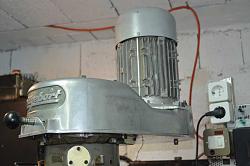
    Originally I used a belt with a length such that the motor was centred over the original motor mounting, but that gave a belt longer than necessary, and at certain rpm the slack side of the belt would vibrate at a resonance. There were two possible solutions to that (if you don't count avoiding the offending rpm). One was to add a tensioning pulley and the other was to move the motor forward and use a shorter belt. I choose the shorter belt route but that required cutting a section out of the top cover and welding it back together. This allowed me to further reduce the height of the forward section of the cover. The above photo to the left shows the arrangement with the longer belt and the other shows the reduced height.

    Conclusion

    I now have a Bridgeport which runs smoothly from zero to 6000rpm. Some expressed concern over the spindle bearings at that speed but it is well within their rating and they only get lute warm. I have heard of a machine rebuilder who converts this type of mill to run at 12,000rpm but I believe that he uses different bearings with a new spindle to take CAT30 tool holders. There is enough room in the stock spindle to take it out to CAT30 and I have thought about how to do it, but it is way down my list of priorities.
    A lot of mechanism has been removed and although the new aluminium cased motor weighs a little more than the old one the overall weight is less and is mounted lower down. This is very noticeable when the head is angled, there is considerably less tendency to rotate further than desired when adjusting an angle.
    Over 5" has been taken off the height and the spindle and draw bar have been shortened by that amount. originally The draw bar nut was too high for me to comfortably tighten and loosen and I fitted a pneumatic draw bar operation. Now it is so easy to use the draw bar manually that I haven't bothered to refit the pneumatic system. It is like I have grown 5"

    186 More Best Homemade Tools eBook
    Last edited by tonyfoale; Feb 14, 2019 at 02:22 PM. Reason: Correct spelling

  2. The Following 17 Users Say Thank You to tonyfoale For This Useful Post:

    C-Bag (Jan 18, 2017), Charron63 (Nov 30, 2017), chy_farm (Jul 30, 2020), emu roo (Sep 3, 2021), Home-PC (Oct 30, 2021), janders1957 (Sep 13, 2019), mudnducs (Jan 17, 2017), mwmkravchenko (Jan 23, 2018), olderdan (Jan 21, 2017), Paul Jones (Jan 18, 2017), rendoman (Jan 17, 2017), rgsparber (Feb 14, 2019), richardcrane (Jan 16, 2017), rossbotics (Feb 2, 2017), Saltfever (Mar 20, 2019), thehomeengineer (Jul 4, 2023), tooly (Sep 13, 2019)

  3. #2
    Supporting Member Ed ke6bnl's Avatar
    Join Date
    Mar 2012
    Location
    So. California high desert
    Posts
    78
    Thanks
    1
    Thanked 14 Times in 11 Posts

    Ed ke6bnl's Tools
    nice work, that would have scared me to death to try but good write up

    2,000+ Tool Plans
    1950 F1 street rod
    1949 F1 stock V8 flathead
    1948 F6 350 chevy/rest stock, no dump bed
    1953 chevy 3100 AD for 85 S10 frame going for a 4BT cummins motor, NV4500
    1968 Baha Bug with 2.2 ecotec motor, king coil-overs,P/S
    2000 National Sea Breeze 5th wheel trailer
    1998.5 Dodge 2500 4x4 Cummins,

  4. #3
    Profkanz's Avatar
    Join Date
    Feb 2016
    Posts
    7
    Thanks
    0
    Thanked 4 Times in 3 Posts
    Quote Originally Posted by tonyfoale View Post
    Requirement and motivation.

    I have a Bridgeport mill which I bought when I lived in the US for a while. The maximum speed shown on the adjusting dial is 4200 rpm but the electricity supply in the US is 60Hz and back here in Spain it is 50Hz so instead of a maximum speed of 4200, all I could hope for would be 3500rpm. Most of my work is with Aluminium with relatively small cutters and 3500rpm is way short of optimum. In addition as the speed of the machine rose above about 2500rpm it rattled and vibrated badly, so I did not like to run it at maximum.
    I decided to dismantle the head to investigate the rattle and to evaluate the feasibility of upping the.maximum rpm. I have ended up with a 6000rpm machine with a 5hp motor in place of the original 1.5hp and 3500rpm. The speed is controlled by a VFD (Variable Frequency Drive) in place of variable pulleys and it runs dead smooth and quiet.

    Click image for larger version. 

Name:	BridgePort_01.JPG 
Views:	1273 
Size:	122.5 KB 
ID:	16127

    Above are the before and after pictures. Note that the height of the top of the cover has been drastically lowered. The LH image shows the original speed adjuster.

    How it was done.

    Click image for larger version. 

Name:	BridgePort_05.JPG 
Views:	843 
Size:	98.4 KB 
ID:	16088 Click image for larger version. 

Name:	BridgePort_06.JPG 
Views:	825 
Size:	114.1 KB 
ID:	16089

    Here we can see the original variable pulley speed variation mechanism. The motor pulley is spring loaded to allow it to adjust the spacing and hence effective diameter. The driven pulley, which sits directly above the spindle, has its spacing controlled by a lever, which in turn is moved by a chain which is pulled by a worm gear system attached to the adjustment handle. This mechanism is shown in the following images.

    Click image for larger version. 

Name:	BridgePort_02.JPG 
Views:	927 
Size:	104.2 KB 
ID:	16090

    Click image for larger version. 

Name:	BridgePort_08.JPG 
Views:	776 
Size:	95.7 KB 
ID:	16091

    The above shows more detail of the drive mechanism to the spindle. The piece to the far right is used but the rest is not in the new drive system.

    Click image for larger version. 

Name:	BridgePort_03.JPG 
Views:	818 
Size:	128.5 KB 
ID:	16092 Click image for larger version. 

Name:	BridgePort_04.JPG 
Views:	1011 
Size:	116.4 KB 
ID:	16093

    With the removal of the main drive pulleys we are left with a view down onto the back gears mechanism, a combination of a gear pair and toothed belt and pulleys. The original intent was to retain the back gears in order to retain the torque multiplication at low speeds but then I realized that I had never had need to use them in the past and decided to go for simplicity. The image to the right shows the cleaned housing (which is no longer required) and the only part of the original drive that will be used. A loose engagement of the face drive dogs, which can be seen near the centre, was responsible for the rattle and rough running at high speeds. I did consider removing the bulk of the gear but decided to leave it to gain some inertia. The teeth on the gear have proved useful for two other features and I am very glad to have retained the gear. I used the teeth to trigger a magnetic sensor for speed measurement and control. The teeth are also used as part of a holding brake, as we'll see later.

    Click image for larger version. 

Name:	BridgePort_07.JPG 
Views:	778 
Size:	103.6 KB 
ID:	16102 Click image for larger version. 

Name:	BridgePort_09.JPG 
Views:	959 
Size:	97.8 KB 
ID:	16103

    With the two housings, one for the back gears and the other for the main drive pulleys no longer in use, we are left with the mounting surface shown above to the left. on the right we see a mounting plate to replace the removed housings and provide a base for the top cover which supports the motor.

    Click image for larger version. 

Name:	BridgePort_10.JPG 
Views:	719 
Size:	103.0 KB 
ID:	16104 Click image for larger version. 

Name:	BridgePort_12.JPG 
Views:	675 
Size:	94.6 KB 
ID:	16105

    Initially I fitted a 2hp DC motor from an exercise treadmill, there was a two fold purpose for this. Firstly I needed to be able to run the mill to do some machining for the conversion, and secondly I was hopeful that it would be man enough to be a permanent solution, but that was regarded as a test. The LH picture shows the motor mounted in temporary fashion to provide the machining capability. The other shows the top cover in place and it is obvious that it is too tall to put a motor support plate on it. So the first task was to machine the top cover down to the correct height.

    Click image for larger version. 

Name:	BridgePort_13.JPG 
Views:	928 
Size:	110.3 KB 
ID:	16110 Click image for larger version. 

Name:	BridgePort_14.JPG 
Views:	683 
Size:	115.7 KB 
ID:	16111

    I used a slitting saw to cut the required amount from the top cover as shown above. This was the first test of the DC motor and it worked pretty well with the large diameter slitting saw.
    ** Encouraging**
    However, I then spotted on a well known auction site a brand new 5hp 3ph motor for 50 euros (it turned out that the seller had entered the wrong price), it was a no-brainer and I bought it immediately.

    Click image for larger version. 

Name:	BridgePort_15.JPG 
Views:	719 
Size:	103.4 KB 
ID:	16113

    Above we have the underside view of the new motor fitted to the top cover. I am a big fan of the poly-V belt, they have plenty of torque capacity in a small size and bend around pulleys with a minimum of effort leading to a very smooth drive. I made the poly-V pulleys from some gears that I had saved from an old lathe.

    Click image for larger version. 

Name:	BridgePort_16.JPG 
Views:	703 
Size:	94.1 KB 
ID:	16116 Click image for larger version. 

Name:	BridgePort_17.JPG 
Views:	913 
Size:	90.2 KB 
ID:	16117

    Here is the driven pulley directly above the main spindle, the spring loaded thingie is a manually operated spindle lock to hold it solid when installing and removing cutters. One of the two uses for the gear teeth that I mentioned earlier.

    Click image for larger version. 

Name:	BridgePort_18.JPG 
Views:	825 
Size:	101.2 KB 
ID:	16109 Click image for larger version. 

Name:	BridgePort_19.JPG 
Views:	865 
Size:	96.9 KB 
ID:	16120

    Originally I used a belt with a length such that the motor was centred over the original motor mounting, but that gave a belt longer than necessary, and at certain rpm the slack side of the belt would vibrate at a resonance. There were two possible solutions to that (if you don't count avoiding the offending rpm). One was to add a tensioning pulley and the other was to move the motor forward and use a shorter belt. I choose the shorter belt route but that required cutting a section out of the top cover and welding it back together. This allowed me to further reduce the height of the forward section of the cover. The above photo to the left shows the arrangement with the longer belt and the other shows the reduced height.

    Conclusion

    I now have a Bridgeport which runs smoothly from zero to 6000rpm. Some expressed concern over the spindle bearings at that speed but it is well within their rating and they only get lute warm. I have heard of a machine rebuilder who converts this type of mill to run at 12,000rpm but I believe that he uses different bearings with a new spindle to take CAT30 tool holders. There is enough room in the stock spindle to take it out to CAT30 and I have thought about how to do it, but it is way down my list of priorities.
    A lot of mechanism has been removed and although the new aluminium cased motor weighs a little more than the old one the overall weight is less and is mounted lower down. This is very noticeable when the head is angled, there is considerably less tendency to rotate further than desired when adjusting an angle.
    Over 5" has been taken off the height and the spindle and draw bar have been shortened by that amount. originally The draw bar nut was too high for me to comfortably tighten and loosen and I fitted a pneumatic draw bar operation. Now it is so easy to use the draw bar manually that I haven't bothered to refit the pneumatic system. It is like I have grown 5"
    Brilliant.

  5. #4
    Supporting Member tonyfoale's Avatar
    Join Date
    Nov 2016
    Location
    Spain
    Posts
    1,607
    Thanks
    721
    Thanked 2,706 Times in 726 Posts

    tonyfoale's Tools
    Quote Originally Posted by Ed ke6bnl View Post
    nice work, that would have scared me to death to try but good write up
    Ed,

    Nothing to be scared of. It is only nuts and bolts and lumps of metal.

  6. The Following User Says Thank You to tonyfoale For This Useful Post:

    thehomeengineer (Jul 4, 2023)

  7. #5
    Content Editor
    Supporting Member
    DIYer's Avatar
    Join Date
    Aug 2013
    Posts
    3,055
    Thanks
    793
    Thanked 1,888 Times in 1,683 Posts


    Thanks tonyfoale! We've added your Mill Motor Modification to our Milling category,
    as well as to your builder page: tonyfoale's Homemade Tools. Your receipt:


  8. The Following User Says Thank You to DIYer For This Useful Post:

    tonyfoale (Jan 20, 2017)

  9. #6
    Content Editor
    Supporting Member
    DIYer's Avatar
    Join Date
    Aug 2013
    Posts
    3,055
    Thanks
    793
    Thanked 1,888 Times in 1,683 Posts


    Thanks tonyfoale! We've added your Mill Pulley to our Machining category,
    as well as to your builder page: tonyfoale's Homemade Tools. Your receipt:


  10. The Following User Says Thank You to DIYer For This Useful Post:

    tonyfoale (Jan 20, 2017)

  11. #7
    mrehmus's Avatar
    Join Date
    Feb 2016
    Posts
    15
    Thanks
    0
    Thanked 11 Times in 5 Posts
    Tony
    Thanks for the article on the Bridgeport. I'm about to work on the same problem although I expect to keep the back gear.
    I have found that using synthetic oil in the spindle bearings allows them to run very cool even for extended periods at maximum speed. Since it is a total loss oiling system on those bearings, I've been using Mobile 1 20-50 weight (which I also use on a large plain bearing lathe for the same reason). Probably 20 or 30 weight oil would be better but the Bridgeport seems to always run fine except, as you noted, the rattle at high speeds.
    Thanks again.
    Mike

  12. The Following User Says Thank You to mrehmus For This Useful Post:

    tonyfoale (Jan 20, 2017)

  13. #8
    Supporting Member marksbug's Avatar
    Join Date
    Apr 2016
    Posts
    1,939
    Thanks
    775
    Thanked 382 Times in 308 Posts

    awesome idea and work.

    [
    thats a great idea and well done too. Ive got a "millport"step pully mill(clone) it needs to come appart and be gone through, but just no time or room to do it now, it's got a 2 speed motor on it, but Ive never been comfeterble running it in high speed due to some of the noise. it was a refurbished mill when I got it... reefer? bush? the x ways were epoxied due to the wear..... must be the reefer part of the rebuild...well I got it cheep so...it is what it is, works great ,someday I will pull it appart and do it right.(reserfacing the ways on a 49x9 may be a chore at home...) I also plan on the tread mill motor mod on my 9x20 enco lathe ( pure **** as it was delevered,gears off center over .010" runout and oh so noisey,quiet as a mouse now, head stock was way out,and much more.no wonder enco closed down 3 months after I got it. I build most of my tooling so fixing this stuff isant hard, just time and room to do it is the hard part.(shop full of race car). this is one of the best sites for ideas.thanks to all who submit this handy work. keep spiten chips and maken mods Tony, we love it.

  14. The Following User Says Thank You to marksbug For This Useful Post:

    tonyfoale (Jan 21, 2017)

  15. #9
    Supporting Member tonyfoale's Avatar
    Join Date
    Nov 2016
    Location
    Spain
    Posts
    1,607
    Thanks
    721
    Thanked 2,706 Times in 726 Posts

    tonyfoale's Tools
    Quote Originally Posted by mrehmus View Post
    Tony
    Thanks for the article on the Bridgeport. I'm about to work on the same problem although I expect to keep the back gear......the Bridgeport seems to always run fine except, as you noted, the rattle at high speeds.
    Thanks again.
    Mike
    Mike,

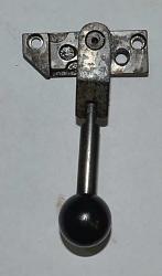
    During the dismantling I found the cause of the rattle on mine. The back gear engage lever did not re-engage the face drive dogs fully when not using the back gears. If I recall correctly there is a sliding piece which can be set to limit the amount of engagement.

    How to make a 6000rpm Bridgeport.-bridgeport_20.jpg
    This is the piece that I talking about.

    A little modification was all that was necessary to allow a fuller engagement and the rattle disappeared. The thing was that I had already decided to make the changes, described in the main post, which removed the need to retain any form of drive engagement/dis-engagement.

  16. The Following User Says Thank You to tonyfoale For This Useful Post:

    olderdan (Jan 22, 2017)

  17. #10
    Supporting Member
    Join Date
    Sep 2018
    Location
    Groningen, NL
    Posts
    44
    Thanks
    322
    Thanked 32 Times in 11 Posts

    Carnel's Tools

    encouraging!

    Quote Originally Posted by tonyfoale View Post
    Requirement and motivation.

    I have a Bridgeport mill which I bought when I lived in the US for a while. The maximum speed shown on the adjusting dial is 4200 rpm but the electricity supply in the US is 60Hz and back here in Spain it is 50Hz so instead of a maximum speed of 4200, all I could hope for would be 3500rpm. Most of my work is with Aluminium with relatively small cutters and 3500rpm is way short of optimum. In addition as the speed of the machine rose above about 2500rpm it rattled and vibrated badly, so I did not like to run it at maximum.
    I decided to dismantle the head to investigate the rattle and to evaluate the feasibility of upping the maximum rpm. I have ended up with a 6000rpm machine with a 5hp motor in place of the original 1.5hp and 3500rpm. The speed is controlled by a VFD (Variable Frequency Drive) in place of variable pulleys and it runs dead smooth and quiet.

    Click image for larger version. 

Name:	BridgePort_01.JPG 
Views:	1273 
Size:	122.5 KB 
ID:	16127 Click thumbnails for full size.

    Above are the before and after pictures. Note that the height of the top of the cover has been drastically lowered. The LH image shows the original speed adjuster.

    How it was done.

    Click image for larger version. 

Name:	BridgePort_05.JPG 
Views:	843 
Size:	98.4 KB 
ID:	16088 Click image for larger version. 

Name:	BridgePort_06.JPG 
Views:	825 
Size:	114.1 KB 
ID:	16089

    Here we can see the original variable pulley speed variation mechanism. The motor pulley is spring loaded to allow it to adjust the spacing and hence effective diameter. The driven pulley, which sits directly above the spindle, has its spacing controlled by a lever, which in turn is moved by a chain which is pulled by a worm gear system attached to the adjustment handle. This mechanism is shown in the following images.

    Click image for larger version. 

Name:	BridgePort_02.JPG 
Views:	927 
Size:	104.2 KB 
ID:	16090

    Click image for larger version. 

Name:	BridgePort_08.JPG 
Views:	776 
Size:	95.7 KB 
ID:	16091

    The above shows more detail of the drive mechanism to the spindle. The piece to the far right is used but the rest is not in the new drive system.

    Click image for larger version. 

Name:	BridgePort_03.JPG 
Views:	818 
Size:	128.5 KB 
ID:	16092 Click image for larger version. 

Name:	BridgePort_04.JPG 
Views:	1011 
Size:	116.4 KB 
ID:	16093

    With the removal of the main drive pulleys we are left with a view down onto the back gears mechanism, a combination of a gear pair and toothed belt and pulleys. The original intent was to retain the back gears in order to retain the torque multiplication at low speeds but then I realized that I had never had need to use them in the past and decided to go for simplicity. The image to the right shows the cleaned housing (which is no longer required) and the only part of the original drive that will be used. A loose engagement of the face drive dogs, which can be seen near the centre, was responsible for the rattle and rough running at high speeds. I did consider removing the bulk of the gear but decided to leave it to gain some inertia. The teeth on the gear have proved useful for two other features and I am very glad to have retained the gear. I used the teeth to trigger a magnetic sensor for speed measurement and control. The teeth are also used as part of a holding brake, as we'll see later.

    Click image for larger version. 

Name:	BridgePort_07.JPG 
Views:	778 
Size:	103.6 KB 
ID:	16102 Click image for larger version. 

Name:	BridgePort_09.JPG 
Views:	959 
Size:	97.8 KB 
ID:	16103

    With the two housings, one for the back gears and the other for the main drive pulleys no longer in use, we are left with the mounting surface shown above to the left. on the right we see a mounting plate to replace the removed housings and provide a base for the top cover which supports the motor.

    Click image for larger version. 

Name:	BridgePort_10.JPG 
Views:	719 
Size:	103.0 KB 
ID:	16104 Click image for larger version. 

Name:	BridgePort_12.JPG 
Views:	675 
Size:	94.6 KB 
ID:	16105

    Initially I fitted a 2hp DC motor from an exercise treadmill, there was a two fold purpose for this. Firstly I needed to be able to run the mill to do some machining for the conversion, and secondly I was hopeful that it would be man enough to be a permanent solution, but that was regarded as a test. The LH picture shows the motor mounted in temporary fashion to provide the machining capability. The other shows the top cover in place and it is obvious that it is too tall to put a motor support plate on it. So the first task was to machine the top cover down to the correct height.

    Click image for larger version. 

Name:	BridgePort_13.JPG 
Views:	928 
Size:	110.3 KB 
ID:	16110 Click image for larger version. 

Name:	BridgePort_14.JPG 
Views:	683 
Size:	115.7 KB 
ID:	16111

    I used a slitting saw to cut the required amount from the top cover as shown above. This was the first test of the DC motor and it worked pretty well with the large diameter slitting saw.
    ** Encouraging**
    However, I then spotted on a well known auction site a brand new 5hp 3ph motor for 50 euros (it turned out that the seller had entered the wrong price), it was a no-brainer and I bought it immediately.

    Click image for larger version. 

Name:	BridgePort_15.JPG 
Views:	719 
Size:	103.4 KB 
ID:	16113

    Above we have the underside view of the new motor fitted to the top cover. I am a big fan of the poly-V belt, they have plenty of torque capacity in a small size and bend around pulleys with a minimum of effort leading to a very smooth drive. I made the poly-V pulleys from some gears that I had saved from an old lathe.

    Click image for larger version. 

Name:	BridgePort_16.JPG 
Views:	703 
Size:	94.1 KB 
ID:	16116 Click image for larger version. 

Name:	BridgePort_17.JPG 
Views:	913 
Size:	90.2 KB 
ID:	16117

    Here is the driven pulley directly above the main spindle, the spring loaded thingie is a manually operated spindle lock to hold it solid when installing and removing cutters. One of the two uses for the gear teeth that I mentioned earlier.

    Click image for larger version. 

Name:	BridgePort_18.JPG 
Views:	825 
Size:	101.2 KB 
ID:	16109 Click image for larger version. 

Name:	BridgePort_19.JPG 
Views:	865 
Size:	96.9 KB 
ID:	16120

    Originally I used a belt with a length such that the motor was centred over the original motor mounting, but that gave a belt longer than necessary, and at certain rpm the slack side of the belt would vibrate at a resonance. There were two possible solutions to that (if you don't count avoiding the offending rpm). One was to add a tensioning pulley and the other was to move the motor forward and use a shorter belt. I choose the shorter belt route but that required cutting a section out of the top cover and welding it back together. This allowed me to further reduce the height of the forward section of the cover. The above photo to the left shows the arrangement with the longer belt and the other shows the reduced height.

    Conclusion

    I now have a Bridgeport which runs smoothly from zero to 6000rpm. Some expressed concern over the spindle bearings at that speed but it is well within their rating and they only get lute warm. I have heard of a machine rebuilder who converts this type of mill to run at 12,000rpm but I believe that he uses different bearings with a new spindle to take CAT30 tool holders. There is enough room in the stock spindle to take it out to CAT30 and I have thought about how to do it, but it is way down my list of priorities.
    A lot of mechanism has been removed and although the new aluminium cased motor weighs a little more than the old one the overall weight is less and is mounted lower down. This is very noticeable when the head is angled, there is considerably less tendency to rotate further than desired when adjusting an angle.
    Over 5" has been taken off the height and the spindle and draw bar have been shortened by that amount. originally The draw bar nut was too high for me to comfortably tighten and loosen and I fitted a pneumatic draw bar operation. Now it is so easy to use the draw bar manually that I haven't bothered to refit the pneumatic system. It is like I have grown 5"
    Couldn't reply without quote...

    Hi Tony, this is splendid for me. The detailed description but specially that you showed one can dare to change machines and upgrade to a premium class device. Thanks for the time you spend to share your experience.

Thread Information

Users Browsing this Thread

There are currently 1 users browsing this thread. (0 members and 1 guests)

Tags for this Thread

Bookmarks

Posting Permissions

  • You may not post new threads
  • You may not post replies
  • You may not post attachments
  • You may not edit your posts
  •