Free 186 More Best Homemade Tools eBook:  
Get tool plans

User Tag List

Results 1 to 6 of 6

Thread: How can you tell if Curent is Flowing?

  1. #1
    Supporting Member BuffaloJohn's Avatar
    Join Date
    Aug 2019
    Location
    Oregon, USA
    Posts
    848
    Thanks
    309
    Thanked 438 Times in 261 Posts

    BuffaloJohn's Tools

    How can you tell if Curent is Flowing?

    I had a situation where I wanted to know if current was flowing to a device. I have a block heater on the tractor and if I plug it in, how do I know that it is operating? I could wait a while and see if it warms up, but it would be nicer if I could tell immediately that current is flowing.

    Just putting an indicator light on the end plug doesn't tell me the heater is running (my plug from the block heater might have failed). I could get a clamp on amp meter and set that up or I could put an amp meter on one of the outlets in the tractor shed which would be dedicated to the block heater or perhaps there was another way - using stuff I already had.

    Turns out, I had a similar problem as I had a pump that I needed to monitor and if the pump stopped running (for whatever reason) I needed to raise an alarm so that yours truly could intervene. For that, I designed a circuit using a current transformer that looks like this:
    How can you tell if Curent is Flowing?-currentindicatorcircuit.jpg

    Vdd is 5v and GND is NOT attached to earth.

    That circuit works really well and can sense the current flowing when the power was down to less than a watt and up to many hundreds of watts (the pump was a variable speed pump).

    For the tractor, I wanted to make it simpler and I came up with this:
    How can you tell if Curent is Flowing?-currentmonitor.jpg

    Pretty simple - 5A/5mA Current Transformer, LED, and Resistor...

    When I bought the current transformer for the pump, at the time it came with a circuit board and you got two sets in the package. You could use the circuit board (I cut in the resistor), but you could also wire it up on a breadboard or even just to the leads of the components.

    The current transformer is an AC device so it's output is AC as well. The HOT line (BLACK in the USA) goes through the hole in the current transformer and the rest of the components are isolated from the line voltage. Most of these current transformers have isolation voltage ratings of thousands of volts (I think mine are 4500V). The orientation of the LED doesn't matter, since it is AC. I put the resistor in there to limit the current in the current transformer and the LED. The value you see is what works well for my block heater. In your case, start higher and lower the value of the resistor until it is bright enough to see the LED. I used an LED that was in my "inventory" (I have no clue of it's specs, it was red and I fussed with the resistor value to get it visible).

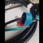
    Here is what it looks like when built:
    the back of the board
    How can you tell if Curent is Flowing?-20231108_161625.jpg

    the front of the board
    How can you tell if Curent is Flowing?-20231108_161637.jpg

    closer view of the front
    How can you tell if Curent is Flowing?-20231108_161650.jpg

    The current transformer I used was a ZTA503C, but just about any 5A/5mA (1000:1) ratio transformer will do. I think a part number I've seen recently is ZMCT103C. Remember you are using a current limiting resistor, so you don't need to scale up to a larger current transformer. There is one on amazon - 10 pieces for $8, another 5 pieces with circuit board for $7. That newer part number shows up on aliexpress as well and pretty cheap.

    186 More Best Homemade Tools eBook

  2. The Following 9 Users Say Thank You to BuffaloJohn For This Useful Post:

    baja (Jun 16, 2024), DIYer (Jun 11, 2024), ductape (Jun 11, 2024), flyfr8rs (Jun 12, 2024), Frank S (Jun 11, 2024), mwmkravchenko (Jun 12, 2024), nova_robotics (Jun 12, 2024), rebuilder1954 (Jun 16, 2024), rlm98253 (Jun 17, 2024)

  3. #2
    Content Editor
    Supporting Member
    DIYer's Avatar
    Join Date
    Aug 2013
    Posts
    3,055
    Thanks
    792
    Thanked 1,880 Times in 1,677 Posts


    Thanks BuffaloJohn! We've added your Current Sensor to our Electrical category,
    as well as to your builder page: BuffaloJohn's Homemade Tools. Your receipt:


    2,000+ Tool Plans

  4. #3
    Supporting Member
    Join Date
    Sep 2018
    Posts
    2,346
    Thanks
    11,132
    Thanked 1,219 Times in 664 Posts

    nova_robotics's Tools
    Looks good, but can I recommend a tiny change? Might want to add some back to back diodes in parallel to that CT to clamp the voltage. With a 3.3k resistor in parallel with that CT you're looking at hundreds of volts across those op-amp inputs if there's in-rush current. Probably won't be a huge problem with a resistive load that only draws an amp or two, but you had mentioned a pump and that will be a problem. Right now you're relying on the chip designer's ESD protection on each pin to save the circuit, but that will only take so many thumps before it gives up and your op-amp kicks the bucket.

    Also you mention using the hot wire, but this circuit will work equally well on hot or neutral. Unless you have a ground fault the current will be identical on both wires and the circuit will function identically.

  5. #4
    Supporting Member jdurand's Avatar
    Join Date
    May 2019
    Location
    Krasnodar Krai, Russian Federation
    Posts
    1,467
    Thanks
    127
    Thanked 766 Times in 425 Posts

    jdurand's Tools
    Depending on the LED used, it may not like being reverse biased every cycle. You could use two LEDs wired in parallel but reversed so one lights at a time or put a diode across the LED to clamp the reversed half cycle.

    The old, dim, green LEDs are really rugged so are often used in a circuit like this to avoid the cost of the diode. More modern LEDs like bright green and others don't like reverse voltage.

  6. #5
    Supporting Member BuffaloJohn's Avatar
    Join Date
    Aug 2019
    Location
    Oregon, USA
    Posts
    848
    Thanks
    309
    Thanked 438 Times in 261 Posts

    BuffaloJohn's Tools
    Quote Originally Posted by nova_robotics View Post
    Looks good, but can I recommend a tiny change? Might want to add some back to back diodes in parallel to that CT to clamp the voltage. With a 3.3k resistor in parallel with that CT you're looking at hundreds of volts across those op-amp inputs if there's in-rush current. Probably won't be a huge problem with a resistive load that only draws an amp or two, but you had mentioned a pump and that will be a problem. Right now you're relying on the chip designer's ESD protection on each pin to save the circuit, but that will only take so many thumps before it gives up and your op-amp kicks the bucket.

    Also you mention using the hot wire, but this circuit will work equally well on hot or neutral. Unless you have a ground fault the current will be identical on both wires and the circuit will function identically.
    I had thought of diodes, but they aren't needed, based on breadboarding and testing. I found that the current transformer saturated at about it's maximum input current. This was found by looking at the scope with only the front end stage of the circuit, with the comparator removed. The traces were clipped, just like if saturation occured. Trust me, I pondered this quite a bit. I suspect that with the datasheet load resistor of 100 ohms max, the results would be more linear, but I didn't test that. I wasn't trying to characterize the current transformer. just experiment with it. So, in practice, the "max current" and the load resistor yielded less than 1.5V. Why? I don't know. 5mA * 3.3k should be 16.5v, but that assumes the current transformer is an ideal inductor and at 60Hz, I don't think it is even close.

    There is 2.5V of headroom because of the voltage divider. I spent a lot of time with the breadboard, loads (resistive and noisy switchers), and a scope testing this because I didn't understand why I couldn't get more current passed to the secondary. I suspect it has to do with the shape of the current transformer and the field around the wire, but Maxwell's equations and EM field theory was 1974 and I don't remember any of it.

    I ended up concluding that while my test loads were 10x of tha actual load, I couldn't force the circuit to get anywhere near the limits of the simple voltage shifter. Also, with the comparator, I was able to detect current at 0.01x the actual load under it's lowest operating point, so given that, diodes were not needed.

    Now, it you had a more powerful current transformer, you wouldn't get away with this circuit, but again, my load was a soft start variable speed pump.

  7. The Following User Says Thank You to BuffaloJohn For This Useful Post:

    nova_robotics (Jun 16, 2024)

  8. #6
    Supporting Member BuffaloJohn's Avatar
    Join Date
    Aug 2019
    Location
    Oregon, USA
    Posts
    848
    Thanks
    309
    Thanked 438 Times in 261 Posts

    BuffaloJohn's Tools
    Quote Originally Posted by jdurand View Post
    Depending on the LED used, it may not like being reverse biased every cycle. You could use two LEDs wired in parallel but reversed so one lights at a time or put a diode across the LED to clamp the reversed half cycle.

    The old, dim, green LEDs are really rugged so are often used in a circuit like this to avoid the cost of the diode. More modern LEDs like bright green and others don't like reverse voltage.
    As I mentioned in a comment about the original circuit, the voltage generated was only around 1.5v, even when I pushed the current way higher than the little current transformer was rated for. The burden resistor was higher than the rated burden resistor. I believe the current transformer was saturated.

    So - even if input current was 3x higher than the rating of the 5A/5mA current transformer (block heater is a 1600w device so current is about 15A), I didn't get much more than about the forward voltage of the diode and the that value as a reverse voltage was not enough to stress the red led I used.

    It's been working for about a decade, so I'm, going to leave it as is.


    2,000+ Tool Plans

Thread Information

Users Browsing this Thread

There are currently 1 users browsing this thread. (0 members and 1 guests)

Bookmarks

Posting Permissions

  • You may not post new threads
  • You may not post replies
  • You may not post attachments
  • You may not edit your posts
  •