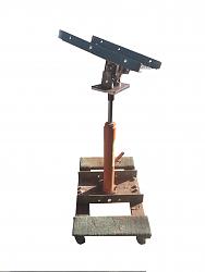
I decided I needed a transmission jack for pulling a couple of automatic transmissions in the near future. I wanted something that I could use with a lift, and that would allow me to tilt the transmission forward or back, and left or right as needed. I wanted a plate to fit under the transmission with method of attaching some tie down straps to secure it to the jack. I also wanted to be able to locate the jacking device under different locations on the plate to account for center of mass of the assembly being somewhere other than the center of the plate. I started with a Harbor Freight long ram flat bottom hydraulic jack #60393. I mounted the jack on a Harbor Freight furniture dolly #63098 using a steel channel bolted to the wood frame of the dolly. This provided the basis for the jack portion with casters to be able to roll around.
The pivoting mechanism is shown a bit closer in this photo. Two 3/8-16 screws are used to adjust and hold the tilt, one for left-right, one for forward-back.
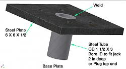
I will show the 3D cad drawings of the assembly to show how it works, and how it goes together. All dimensions are somewhat arbitrary and can be adjusted to what you have to work with. First I fabricated a short length of steel tubing to fit over the ram, and welded it to a steel plate, 6 x 6 x 1/2 ".
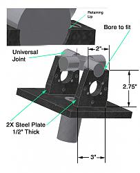
This base plate slips over the ram but has a small enough bore to prevent the ram going all the way through. I used the guts from a universal joint I had on hand, I think it fits a F150 Ford, but any universal joint could be adapted with some minor dimension changes. Next step is to fabricate some mounts to add to the plate. Note that the mount is bored to fit the bearing cup on the universal, with a lip to prevent sideways motion of the bearing cups.
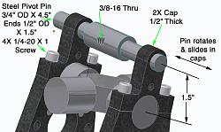
Then add some caps to hold the thing together. The caps have an extension for attaching the tilting mechanism. I used a center to center distance of 1 1/2 inches which seems to be about right for tilting. The steel pivot pin is turned down on both ends and is designed to slide in the caps as well as rotate during adjustment. It may not be obvious, but the pin must slide when the opposite direction of tilt is applied. The large diameter of the pin is about 1 1/2 inches long, and each end section needs to be at least 1 1/2 inches.
The adjusting screw is a 3/8-16 x 3 1/2 inch long full thread bolt for my situation. If your dimensions vary, the length may be different. It fits into another pivot pin that attaches in two steel pivot blocks bolted to the mount. A locking (Nylok) nut was used to retain the screw to the pin, but other methods would work. The screw needs to be snug fitting to the pin, but still free to rotate. The large hole in the mount is to provide clearance for the locking nut over the full range of motion. The short pin fits between the blocks with minimum clearance on the ends. The ends are turned down to 7/16" to clear the 10-32 screws located 3/4" apart vertically.
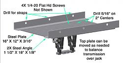
Another identical assembly is fabricated for the other direction of tilt. It is identical to the bottom assembly except for the 6x6 plate is only 1/4 inch thick, and it has tapped holes on the corners for mounting the top transmission plate. The transmission plate is drilled on a grid of 2 x 2 inches to allow bolting it to the top plate in various locations to achieve the best balance. If a transfer case is attached to one side of your transmission, you probably will want to position the jack ram offset to get it closer to the balancing point of the assembly. Angle iron side fixtures stiffen the transmission plate and provide a location to hook a chain or other hold down strap to keep the transmission assembly from slipping around on the plate.
The finished assembly slips over the ram of the jack. I estimate the assembly can be tilted about +/- 30 degrees in either direction and can easily be adjusted simply by turning the 3/8 screws with a socket or open end wrench.
Of course you could adapt this tilting mechanism to a floor jack or shorter hydraulic jack if you wanted to work without a lift.


 LinkBack URL
 About LinkBacks




 Reply With Quote


Bookmarks