Free 186 More Best Homemade Tools eBook:  
Get tool plans

User Tag List

Page 1 of 6 1 2 3 4 5 6 LastLast
Results 1 to 10 of 58

Thread: Homemade Tool & Cutter grinder (with a difference).

  1. #1
    Supporting Member tonyfoale's Avatar
    Join Date
    Nov 2016
    Location
    Spain
    Posts
    1,607
    Thanks
    721
    Thanked 2,706 Times in 726 Posts

    tonyfoale's Tools

    Homemade Tool & Cutter grinder (with a difference).

    My Tool & Cutter grinder.

    I have always lusted after a Tool and Cutter (T&C) grinder. I don’t know why, but who can explain love, after all it is just a tool for sharpening blunt drills and milling cutters. Not very exciting, and I’d have more use for a cylindrical or surface grinder. Anyway a few months back I took the bull by the horns and made one which incorporated a few of my ideas for a mechanical simpler machine than the norm but without any sacrifice of functionality.

    NOTE: For reasons unknown to me the next three photos refuse to display. I have posted them again in post #4 below.

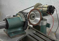
    Attachment 15826

    The basics

    Three existing items formed the base components of this machine. I had previously built a tool post grinder for my lathe but it was made with a consideration that it might prove useful to be able to attach it to other machines as well. A T&C grinder had been rattling around in the deeper recesses of my mind for quite some time, and the tool post grinder was the final piece of the puzzle.

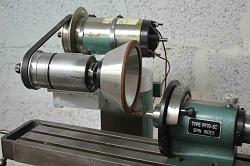
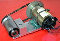
    A while back I bought, at a flea market, what appeared to be a quill and spindle from a small mill/drill machine. I knew it would be useful one day and it was cheap as well. The spindle had an internal Morse taper No. 2 which was ideal for the grinding wheel arbours as we’ll see. It was as if it was made for my grinder. To power it I wanted a variable speed motor. Options for that were a small 3 phase motor with a variable frequency drive for control or a DC motor which could be controlled by the applied voltage. I had a 2hp DC motor from an exercise treadmill and I decided to use that. The following picture illustrates how the grinding head was constructed from those parts plus some aluminium from the scrap box.

    DC motors have their speed controlled by the applied voltage, for initial testing I simply used a Variac (a variable voltage auto-transformer). Later I made a PWM (Pulse Width Modulation) system for control, I used a double 555 timer chip to provide the variable width timing pulses which were sent to the motor control MOSFET through a gate driver chip for fast switching. Very simple, very few components and which are dirt cheap these days.

    Attachment 15827

    The grinding head, showing the re-purposed mill/drill quill and spindle on the left and the DC motor salvaged from an exercise machine, on the right. The large hole in the aluminium block is to mount the assembly in place of a lathe tool post. Note the MT2 taper in the spindle.

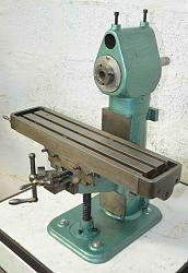
    I also had a small horizontal milling machine which I made from scratch in the 1960s. It hadn’t been used for 50 years and looked to be in poor shape but after dismantling and cleaning it came up as new. It was an ideal platform on which to mount the grinding head to make a capable T&C grinding machine. The mill was described on this forum in a prior posting.

    Attachment 15828

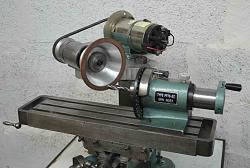
    The small horizontal milling machine which I made around 55 years ago. A good clean and a coat of paint had it back to its former glory. The milling head will be replaced with the tool post grinder head.

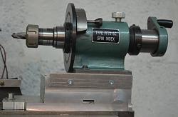
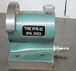
    The third item to complete the machine is a what is called a Spin Indexer (or Spindexer). Which is a holding fixture with a vernier adjustment which allows rotary motion in 1 degree increments. It comes with a through hole to take 5C collets. I also have an ER25 chuck with a 5C arbour so overall I am well covered to hold drills and milling cutters from 1mm to 25mm. This indexer will allow drill bits and milling cutters etc. to be rotated about their own axis to present the cutting edges in turn to the grinding surface.
    I made some modifications to improve the spindexer which are outlined in Appendix 1, at the end of this document.

    Homemade Tool & Cutter grinder (with a difference).-tandc-grinder-01.jpg

    An aluminium block is the mounting for the grinding head. It is spigoted to the vertical mill column and can rotate about a Z-axis. The block is offset to the left to reduce the needed overhang of the mill table and indexer. The Spin Indexer is mounted directly to the mill table, this will be changed later.

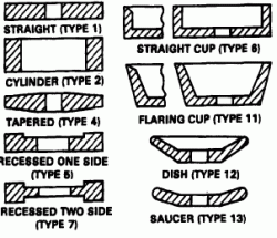
    The only items that I didn’t already have were suitable grinding wheels. There are many shapes of wheel available for T&C sharpening but unless you are sharpening tools on a frequent basis it becomes uneconomic to keep a wheel for every type of required cut. I choose to get identical flaring cups, one of CBN and another of diamond. Flaring cups are a good overall compromise and allow most types of cutting. CBN is great for steel tools, it cuts cool and can be used dry or with liquid coolant, it has high metal removal rates and wears very little itself. Diamond is the abrasive of choice for use with tungsten carbide tools, but is unsuitable for steel.
    Homemade Tool & Cutter grinder (with a difference).-wheel-types.gif
    Here are some common wheel shapes used for T&C work.

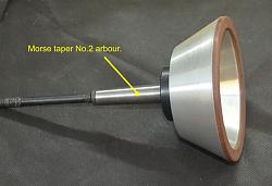
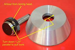
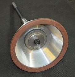
    The smaller industrial grinding wheels like these generally have a 1.25” (31.75mm) mounting hole. Rather than remove each wheel from a single arbour when a wheel change is necessary I decided to mount each wheel on its own arbour and then change wheels and arbours together in the interests of accuracy and repeatability. This was the main advantage of using a spindle with a MT2 taper. The easiest and quickest way to get suitable arbours was to use standard arbours made for boring heads, modified by turning the mounting down to 1.25”.
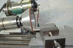
    Homemade Tool & Cutter grinder (with a difference).-tandc-grinder-0.jpg Homemade Tool & Cutter grinder (with a difference).-tandc-grinder-35b.jpg Homemade Tool & Cutter grinder (with a difference).-tandc-grinder-35.jpg

    Left shows the threaded arbour for a boring head. The thread was turned off down to a parallel diameter of 1.25” to suit the wheels.The others show the assembled wheel and arbour complete with a draw bar to hold the taper into the grinder spindle.

    How others do it

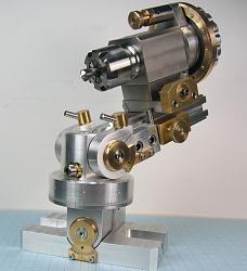
    Many (most?) tool and cutter grinders use multi-axis tool holding systems, mostly 3 overall axis plus a spin axis for indexing the tool bit as shown in this beautiful piece of mechanical art below.

    Homemade Tool & Cutter grinder (with a difference).-mini_bonelle_ii_806.jpg

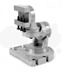
    For the lazy, you can buy a 3 axis work holder for less than $100 on eBay, as per the following, and I did consider this option. The top section could easily be machined to take the spindexer to provide the tool indexing function.

    Homemade Tool & Cutter grinder (with a difference).-universal-mtg2.jpg

    Why I do things differently.

    However, I am a great lover of simplicity and a little knowledge of 3D geometry led me, a long time ago, to realize that as fascinating as these 4 axis system are, they are totally unnecessary. You can achieve the same results with a single global axis plus the indexing axis, thereby cutting down on fabrication work by a large margin. How is this possible and why doesn’t everyone do it? The first is explained in the following but the second question eludes me, maybe it’s a case of “it has always been done that way”.

    Consider the face of a grinding wheel as a flat plane, and as an example let’s think about grinding a drill bit with a 4 facet grind. (For those unfamiliar with 4 facet drill bits, I suggest asking Mr. Google, he has lots of info. on the subject.) We want to present the drill bit to the wheel such that it touches the wheel at the required nose angle and also the required clearance angle. So with the traditional multi-axis machines we would probably use the indexing axis to set the cutting edge either horizontally or vertically depending on the specific machine. Then we would set one global axis to the nose angle and another axis to the clearance angle. Simple and very understandable. However, no matter how many angles the tool bit is moved through in the end the bit’s axis will form a single angle to the plane of the wheel’s face, so we only need a single global axis to present the tool to the wheel at the combined angle of the two movements. Too good to be true? Yes it is, if that that is all that we did then the cutting edge of the bit would be given a clearance angle of zero, we can get around that problem by twisting the bit around its own axis. So now all we need is a single global axis and the indexing or twist axis of the tool. A bit of trigonometry is all that is required to calculate what those angles should be given the nose and clearance angles that we are after, and I made a spreadsheet to do the heavy lifting. This principle can be applied to other types of tools such as end mills and even lathe tools.

    I made this T&C grinder a few months ago and by way of explanation to some friends over the net I made a few videos explaining how this angle juggling works. These videos are about 5 mins each. Bear in mind that a few comments were directed at my friends based on prior correspondence, the videos were not scripted beforehand and so parts may not flow smoothly. I suggest that they be viewed in the order presented here.

    This is the first part explaining the magic of the disappearing axes.
    https://motochassis.com/FileDump/Tan...r/TC part1.MOV

    next is part 2, which has the stuff that that I forgot in part 1.
    https://motochassis.com/FileDump/Tan...r/TC part2.MOV

    4 facet drill bit sharpening
    https://motochassis.com/FileDump/Tan...rill4facet.MOV

    The next video shows how the logic of the 2 axes system can be applied to an end mill.
    https://motochassis.com/FileDump/Tan...r/TC part3.MOV

    Sharpening a ball end cutter
    https://motochassis.com/FileDump/Tan...er/BallEnd.MOV

    Finally, we see how it also can be applied to a lathe tool.
    https://motochassis.com/FileDump/Tan.../LatheTool.MOV


    See Appendix 2 for a more complete verbal explanation.

    The implementation

    The construction and manner of use of my T&C grinder evolved over the short period of the few days of its construction. Normally, I tend to think through every aspect of something that I am about to make but in this case I didn’t. I started making it without much prior thought and as a result I had to make a few changes along the way. There were basically 3 iterations.

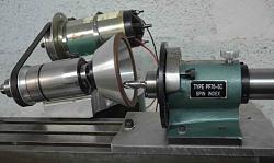
    The first saw the Spindexer bolted directly to the mill table with the grinding head able to rotate about a vertical Z-axis. This allowed the stone to be presented to the tool at appropriate angles to get the rake and clearance angles required. This arrangement enabled the vast majority of bits and cutters to be ground but a notable exception was rounded nose cutters. To grind such tools it is necessary to be able to rotate the tool point itself about a vertical axis. That on its own was insufficient though, as it would be impossible to grind the clearance angle equally around the curved nose.

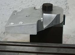
    The next iteration was to solve those problems. The Spindexer was mounted on a plate which could rotate about a vertical pivot bolt and the grinding head was then rotated a fixed amount about a horizontal Y-axis by machining its mounting plate at a 7 degree angle, which is a good compromise 1st clearance angle for many tools. The machine now did a good job of ball ended cutter as well as drill bits, end mills and slot drills but it lost the ability to face off a badly damaged tool flat at 90 deg. to clean it up to start over. It also became less suitable for grinding the flutes of tools.

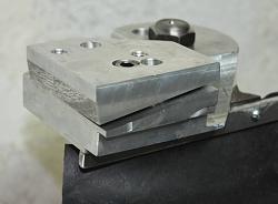
    The third and hopefully final iteration had the Spindexer raised up on a block to achieve more clearance under the grinding wheel, when fitted with a cover. The block at 45mm high is taller than necessary but it was the most suitable piece in the scrap box. Another change was the insertion of a removable wedge shaped spacer under the grinding head. This spacer brought the spindle axis back to horizontal, but the simple removal of the spacer allows the return to an angled wheel face permitting the sharpening of rounded nose cutters.

    Although the grinding head still has the ability to rotate about the vertical Z-axis, I have yet to encounter a situation where this would help in the 3rd and current iteration.

    Homemade Tool & Cutter grinder (with a difference).-tandc-grinder-03.jpg

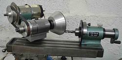
    First design iteration. The Spindexer is bolted directly to the mill table and has no angular degrees of freedom other than about the tool axis. On the other hand the grinding head has been rotated about a vertical Z-axis by the value of the required clearance angle on the end mill. This arrangement worked perfectly but was incapable of grinding round nose cutters.
    Homemade Tool & Cutter grinder (with a difference).-tandc-grinder-07.jpg Homemade Tool & Cutter grinder (with a difference).-tandc-grinder-05.jpg

    Two possibilities for sharpening a drill bit to the 4 facet specification with the 1st iteration design. Note in the left photo that the mill table and Spindexer are forced into a position with a lot of overhang. This is not a good setup for such a small machine and the other option is preferable and has the added bonus of improved visibility at the cutting edge.
    Homemade Tool & Cutter grinder (with a difference).-tandc-grinder-10.jpg Homemade Tool & Cutter grinder (with a difference).-tandc-grinder-10b.jpg Homemade Tool & Cutter grinder (with a difference).-tandc-grinder-10c.jpg

    Grinder mounting block after being machined at an angle of 7 deg. So far this has only been used for sharpening radiused cutters. The other pix. show the wedge shaped spacer which, when fitted, returns the wheel face to the vertical.

    Homemade Tool & Cutter grinder (with a difference).-tandc-grinder-16b.jpg

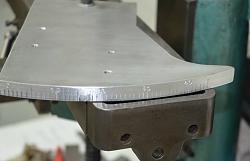
    Mounting plate for the spindexer. Pivoted about a vertical axis, just visible at the top of the photo. Graduated 0 to 45 deg.
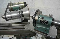
    Homemade Tool & Cutter grinder (with a difference).-tandc-grinder-14b.jpg Homemade Tool & Cutter grinder (with a difference).-tandc-grinder-15.jpg Homemade Tool & Cutter grinder (with a difference).-tandc-grinder-14a.jpg

    The above 3 photos show the rotation of the spindexer about a vertical axis to grind all the way around the end of a ball ended cutter.

    Homemade Tool & Cutter grinder (with a difference).-tandc-grinder-28.jpg

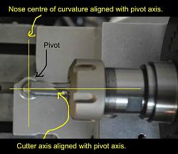
    Here we can see how the centre of the radius on the end a ball ended cutter needs to be aligned with the vertical pivot axis of rotation of the mounting plate of the spindexer.
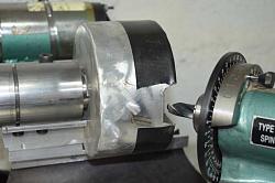
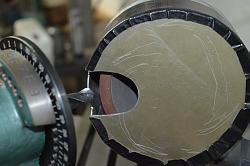
    Homemade Tool & Cutter grinder (with a difference).-cover-01.jpg Homemade Tool & Cutter grinder (with a difference).-cover-03.jpg

    Once that I had established that the tool was working OK I fashioned up a cover for the wheel from some sheet aluminium off-cuts that I had left from making some motorcycle fuel tanks. Not visible in these photos is a tube welded to the rear of the cover for connection to a shop-vac. That catches ALL the grinding dust and the rest of the machine requires no additional protective covering. The Gorilla tape fixing of the outer cover was just a temporary measure while I experimented with the size of the opening. I wanted to keep it as small as possible to keep the entrance air velocity high to carry all dust in, but I needed it large enough not to hinder access for the tool nor hinder vision.

    ***** I couldn't get any more photos to load. Maybe I exceeded a limit, so I'll try and continue in a following post.*******

    186 More Best Homemade Tools eBook
    Last edited by tonyfoale; Mar 20, 2019 at 04:42 PM. Reason: Correct a caption.

  2. The Following 18 Users Say Thank You to tonyfoale For This Useful Post:

    12L14 (Jul 31, 2019), asterix (Feb 17, 2023), emu roo (Nov 11, 2024), high-side (May 8, 2019), HobieDave (Mar 13, 2020), Home-PC (Jan 13, 2021), Hopefuldave (Feb 1, 2020), jjr2001 (Jan 15, 2017), LMMasterMariner (Mar 21, 2019), markcawston (Apr 12, 2019), Okapi (Jun 27, 2017), Saltfever (Nov 25, 2023), Scotsman Hosie (May 8, 2019), Sleykin (Jan 28, 2021), that_other_guy (Jan 4, 2019), thehomeengineer (Feb 18, 2020), Tonyg (Oct 23, 2018), tooly (Feb 6, 2020)

  3. #2
    Supporting Member tonyfoale's Avatar
    Join Date
    Nov 2016
    Location
    Spain
    Posts
    1,607
    Thanks
    721
    Thanked 2,706 Times in 726 Posts

    tonyfoale's Tools
    ************ To continue

    Homemade Tool & Cutter grinder (with a difference).-tandc-grinder-31.jpg

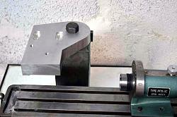
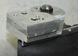
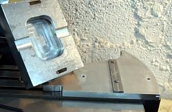
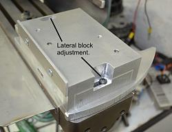
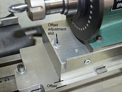
    I hadn’t considered a wheel cover originally and when fitted it prevented lifting the table and spindexer to the required height. As shown above this was solved by lifting the spindexer with the aid of an aluminium block. The block came out of the scrap box and was thicker than strictly necessary at 45mm. I could have milled it thinner but there was no disadvantage with leaving it thick. The addition of this block allowed me add the ability to offset the spindexer laterally (Y axis). I have already described the necessity of aligning the spindexer axis directly above the pivot axis of the mounting plate for ball end cutters. However, that is no good for doing cutters which just have rounded edges rather than being full ball nosed. To grind rounded edge cutters the tool bit has to be offset laterally such that the centre of curvature is aligned vertically with the pivot axis.

    The following photos show details of the block and the slide and groove used to maintain alignment. The pocket in the base of the block is just a legacy of the block’s previous life.

    Homemade Tool & Cutter grinder (with a difference).-tandc-grinder-34.jpg Homemade Tool & Cutter grinder (with a difference).-tandc-grinder-32.jpg Homemade Tool & Cutter grinder (with a difference).-tandc-grinder-33.jpg

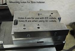
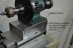
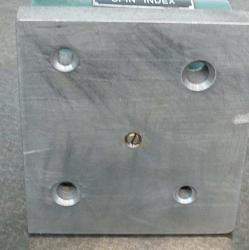
    The above show details of the block lateral fixing method. Note also the two pairs of mounting holes for the spindexer. The forward pair are for use when using 5C collets for tool holding and the rearward pair are when the ER25 collets are used. The side fence on the front of the block is for easy alignment of the spindexer when moved fore and aft.

    Homemade Tool & Cutter grinder (with a difference).-tandc-grinder-29.jpg Homemade Tool & Cutter grinder (with a difference).-tandc-grinder-30.jpg

    These show the assembled spindexer and mounting block etc. The relevant parts and adjustments are annotated.

    Results

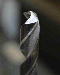
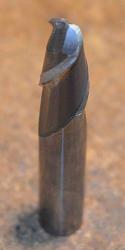
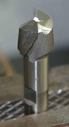
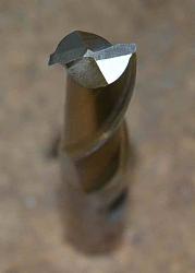
    Homemade Tool & Cutter grinder (with a difference).-facet4.jpg Homemade Tool & Cutter grinder (with a difference).-tandc-grinder-18.jpg Homemade Tool & Cutter grinder (with a difference).-tandc-grinder-08a.jpg Homemade Tool & Cutter grinder (with a difference).-tandc-grinder-09.jpg

    Here are some examples of tools sharpened as test items during the rapid evolution of this T&C grinder.

    Homemade Tool & Cutter grinder (with a difference).-tandc-grinder-19.jpg Name:  cs 04.jpg
Views: 18021
Size:  11.3 KB

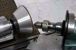
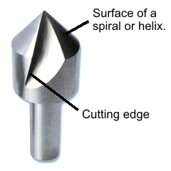
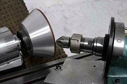
    Demonstrating how a multi-toothed countersink bit is ground. Unfortunately, a single flute version such as the one to the right is not so easy. The smooth surface back away from the cutting edge is not a true cone shape but is a section of a spiral or helix. A cone would not cut properly, the bit would just rub. Therefore it becomes necessary to advance the bit into the grinding wheel as it is rotated. There are different ways to do this but with a spindexer the most obvious way is by means of a face cam. I have not implemented that yet and it will probably wait until I have a bunch of those to refresh. In any case as long as the spiral/cone surface is not damaged these bits can be sharpened by grinding on the cutting edge.

    Homemade Tool & Cutter grinder (with a difference).-tandc-grinder-23.jpg Homemade Tool & Cutter grinder (with a difference).-tandc-grinder-26.jpg

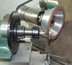
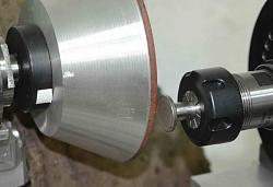
    Although built to be a T&C grinder I have found several other uses for it. Two of which shown above. One show it being used to reface a valve. I have a dedicated valve grinder and I had spent some time in the past looking at it with a view to using it as the base for the T&C grinder, but I never found a good way of doing it. Otherwise this post would have been describing that. The other photo shows it facing off a tappet base, It did a great job of that.

    Homemade Tool & Cutter grinder (with a difference).-tandc-grinder-22.jpg

    More versatility is shown here doing a good job on a HSS lathe tool. Although this method worked well with no problems I later bought a ½” square 5C collet which is more in keeping with its use for other tools and makes setting angles much easier.
    A video of the square collet used with a lathe tool is at
    https://motochassis.com/FileDump/Tan.../LatheTool.MOV

    Conclusion.

    One test of how well you have done something is to ask, at the end of some period of use, “With hindsight what would I have done differently?”. In the case of the T&C grinder there is only one thing. If I was doing it again I would mount the grinding head such that I could rotate it about a horizontal Y-axis. I have ended up with just two possible positions depending whether I have the wedge spacer inserted or not. In practice that works fine and only needs to be changed for rounded end cutters, but a head that rotated would be the icing on the cake. That could always be retro-fitted if the mood takes me.
    In general it was an interesting project which didn’t take long to make due largely to using what I had and I don’t have a blunt tool in the shop. Drill bits below around 2mm are still done in a Drill Doctor and milling cutters below 3mm just get replaced with new.
    Any tool like a mill or mill-drill could be used as a base for a similar machine, Turntable in his “Homemade surface grinder” posting showed us a rigid method of mounting a grinding head to a large mill. There are many suitable options for the grinding head, even a small bench grinder could be used and the Spindexers can be bought off eBay for $40 or so.

    Appendix 1– modifications to the spindexer

    In common with many tools from the east, I regarded the spindexer as a kit of assembled parts which needed finishing.

    My first task was to dismantle spindexer and machine all surfaces, the base and side/end edges, true to the spindle bore. The bore itself was pretty good and parallel as far as I could measure it. I made a mandrel that fitted the bore and used that as the reference for the other machining operations. I can now trust the alignment of the device.

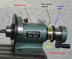
    The second thing that needed attention was the method of end float control of the rotating hollow shaft. The stock system is a collar on the rear of the shaft which is held in place by 3 grub screws. It was next to impossible to set this to zero end float without making it stiff and notchy to rotate. End float can affect the depth of the grinding cut and so it is important to remove it to achieve equal height cutting edges on multi-flute tools. The following shows how I proposed a spring loaded collar system to take care of the end float.

    Homemade Tool & Cutter grinder (with a difference).-collar-02.jpg

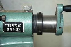
    As it turned out I couldn’t find a suitable sized spring but I did have a bunch of X section O-rings, so I packed a few of those on the shaft in place of the proposed spring and said goodbye to end float problems. The following shows the actual solution with the stack of O-rings in front of the original collar.

    Homemade Tool & Cutter grinder (with a difference).-collar-03.jpg

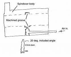
    The final modification is to help with grinding the flutes of end mills and reamers. So far the examples shown for grinding tools have focussed on the end cutting edges but side cutting milling tools, drill bits and reamers also get worn on the flutes. Drill bits, mostly have their flute wear near the cutting end and we also rely on drill bits being a given diameter. So often it is better to simply cut off the end part and regrind only the tip. Reamers also are important to be a specified size but they tend to wear over a lot of their length so the only real reclaiming option is to grind the reamer down to the next useful diameter. Milling cutters, on the other hand, are still useful even when ground a little undersize. In order to cut helical flutes it is necessary to move the bit being sharpened along its axis at the same time as rotating it. To allow axial motion with the spindexer it is only necessary to remove the end float collar (and O-rings in my case). The shaft can be moved radially and axially. A stop is used on one flute to maintain the correct helix angle as the tool is fed along the grinding wheel. To achieve a smooth and accurate action whilst doing this double movement, it is necessary to have as friction free and smooth action as possible. The stock spindexer motion wasn’t bad but I thought that it could be improved by making the spindle float on air – turn it into an air bearing. To this end I machined a groove around the inside of the spindexer bore and drilled some holes to feed it with air as shown in this sketch.

    Homemade Tool & Cutter grinder (with a difference).-airbearing-03.jpg

    I have designed flat surface air bearing before and so I knew a tad about the requirements. To get a successful efficient air bearing it is not just sufficient to feed air to a groove, at some pressures it might seem to work OK until loaded. It is necessary to feed the air in through a restriction fed from a reservoir. Larger feed pipes are usually sufficient for this. In order to have some setup tuning capability I made an adjustable restrictor as shown above. I put Loctite on the threads, and adjusted the screw for the best action and let the Loctite set.
    Without the air feed the shaft will rotate between a half and a full revolution when spun by hand, with the air bearing working it will spin for several turns and the whole action is much smoother. Air consumption is minimal and with fading hearing I can’t hear the air exiting, but my dogs can. The air bearing is only used when doing flutes, it is not necessary for normal point sharpening.

    Appendix 2 – Explanation of single angle setting

    I had a hard time believing how complex the usual multi-axis T&C grinders were. It was the idea of cutting down on the number of independent axes to making just two that appealed to me. Just as if you want to move on an X,Y plane from 0,0 to 10,25 you can do it the long way and move to 10, 0 and then 10, 25 or the easy way in a single shorter diagonal move direct to 10, 25. You can do the same with angles. A simple calculation results in a single angle between the drill bit and the face of the wheel.
    Imagine a plain flat rest set at 90deg to the face (side) of the wheel, then lay the drill bit on that with the cutting edge horizontal and the drill angled on the rest such that the whole cutting edge is touching the wheel. If you ground the bit like that you'd get zero clearance angle, but now rotate the bit about its own axis. Now you have a non zero clearance angle but the outside edge will have pulled away from the wheel, now angle the bit a little until all the cutting edge is touching. In that position you only have to plunge the bit into the wheel to grind the first facet of a 4 facet bit. Twist the bit some more and re-angle it and you can grind the next facet with more clearance.
    So instead of a relatively complex sharpener all you need to do to grind a 4 facet bit is to mount your drill in some form of holder which can rest on a horizontal plane normal to the wheel and be angled sideways and with provision to rotate the bit about its own axis. I see a $40 spin indexer fitted with an ER25 collect chuck as the bit holder.
    To use, just insert the bit in the chuck, angle and rotate it according to the calculations for the required bit included angle and clearance angle and plunge into the wheel up to a set stop or other means of determining the grinding depth. Or else you could feed the wheel to the work.

    Appendix 3 – List of videos

    I suggest that they be viewed in the order presented here.

    This is the first part explaining the magic of the disappearing axes.
    https://motochassis.com/FileDump/Tan...r/TC part1.MOV

    next is part 2, which has the stuff that that I forgot in part 1.
    https://motochassis.com/FileDump/Tan...r/TC part2.MOV

    4 facet drill bit sharpening
    https://motochassis.com/FileDump/Tan...rill4facet.MOV

    The next video shows how the logic of the 2 axes system can be applied to an end mill.
    https://motochassis.com/FileDump/Tan...r/TC part3.MOV

    Sharpening a ball end cutter
    https://motochassis.com/FileDump/Tan...er/BallEnd.MOV

    Finally, we see how it also can be applied to a lathe tool.
    https://motochassis.com/FileDump/Tan.../LatheTool.MOV

    See Appendix 2 for a more complete verbal explanation of the 4 facet sharpening..

    2,000+ Tool Plans

  4. The Following 24 Users Say Thank You to tonyfoale For This Useful Post:

    asterix (Feb 17, 2023), bigtrev8xl (May 8, 2019), C-Bag (Jan 6, 2017), Canyonman44 (Dec 28, 2019), Charron63 (Nov 30, 2017), DIYSwede (Aug 10, 2019), Home-PC (Jan 13, 2021), Hopefuldave (Feb 1, 2020), J.Pierce (Oct 19, 2019), jjr2001 (Jan 15, 2017), LMMasterMariner (Mar 21, 2019), Lornie (Jan 10, 2017), markcawston (Apr 12, 2019), mwmkravchenko (Jan 7, 2022), olderdan (Jan 6, 2017), Paul Jones (Jan 6, 2017), Saltfever (Nov 25, 2023), Scotsman Hosie (May 8, 2019), Sleykin (Jan 28, 2021), that_other_guy (Jan 4, 2019), thehomeengineer (Feb 18, 2020), Tonyg (Oct 23, 2018), Toolmaker51 (Feb 8, 2017), tooly (Feb 16, 2020)

  5. #3
    Supporting Member tonyfoale's Avatar
    Join Date
    Nov 2016
    Location
    Spain
    Posts
    1,607
    Thanks
    721
    Thanked 2,706 Times in 726 Posts

    tonyfoale's Tools
    Here are a couple of photos to go with the sketch of the air bearing modifications.

    Homemade Tool & Cutter grinder (with a difference).-airbearing-04.jpg Homemade Tool & Cutter grinder (with a difference).-airbearing-05.jpg

  6. The Following 6 Users Say Thank You to tonyfoale For This Useful Post:

    asterix (Feb 17, 2023), jjr2001 (Jan 15, 2017), olderdan (Jan 6, 2017), Scotsman Hosie (May 8, 2019), thehomeengineer (Feb 18, 2020), tooly (Feb 16, 2020)

  7. #4
    Supporting Member tonyfoale's Avatar
    Join Date
    Nov 2016
    Location
    Spain
    Posts
    1,607
    Thanks
    721
    Thanked 2,706 Times in 726 Posts

    tonyfoale's Tools
    The first 3 photos did not show in the original post, and the edit system wouldn't let me load replacements????
    So here they are hopefully.

    Homemade Tool & Cutter grinder (with a difference).-tandc-grinder-19.jpg

    Homemade Tool & Cutter grinder (with a difference).-tp-grinder-12.jpg

    Homemade Tool & Cutter grinder (with a difference).-smallmillasm-11.jpg

  8. The Following 13 Users Say Thank You to tonyfoale For This Useful Post:

    aphilipmarcou (Feb 10, 2017), Canyonman44 (Dec 29, 2019), DIYSwede (Jun 29, 2019), Hopefuldave (Feb 1, 2020), jjr2001 (Jan 15, 2017), mwmkravchenko (May 7, 2019), olderdan (Jan 6, 2017), Paul Jones (Jan 6, 2017), Scotsman Hosie (May 8, 2019), that_other_guy (Jan 4, 2019), Tonyg (Oct 23, 2018), tooly (Feb 16, 2020), Vyacheslav.Nevolya (Jan 12, 2017)

  9. #5
    Supporting Member olderdan's Avatar
    Join Date
    Jun 2016
    Posts
    793
    Thanks
    1,463
    Thanked 1,585 Times in 470 Posts

    olderdan's Tools
    Amazing work as usual, I do connect with your logical approach and your explanations that even I can understand.
    Tool and cutter grinding ( once a job title in itself ) has for me always been a bit of a black art, I have a large box of worn cutters that I have had for years so I think I will now try to make use of them.
    I'm guessing three in a row.
    Regards
    Olderdan

  10. The Following 2 Users Say Thank You to olderdan For This Useful Post:

    jjr2001 (Jan 15, 2017), tonyfoale (Jan 6, 2017)

  11. #6
    Supporting Member tonyfoale's Avatar
    Join Date
    Nov 2016
    Location
    Spain
    Posts
    1,607
    Thanks
    721
    Thanked 2,706 Times in 726 Posts

    tonyfoale's Tools
    Quote Originally Posted by olderdan View Post
    I'm guessing three in a row.
    Didn't happen. I have got to up my game.

  12. The Following User Says Thank You to tonyfoale For This Useful Post:

    jjr2001 (Jan 15, 2017)

  13. #7
    Supporting Member tonyfoale's Avatar
    Join Date
    Nov 2016
    Location
    Spain
    Posts
    1,607
    Thanks
    721
    Thanked 2,706 Times in 726 Posts

    tonyfoale's Tools
    Quote Originally Posted by olderdan View Post
    Amazing work as usual, I do connect with your logical approach and your explanations that even I can understand.
    Tool and cutter grinding ( once a job title in itself ) has for me always been a bit of a black art, I have a large box of worn cutters that I have had for years so I think I will now try to make use of them.
    In the industrial world tool & cutter grinding has changed a lot. Many shops now just buy new cutters and scrap the blunt ones. maximum production from CNC machines demands super sharp cutters of precise dimensions. Very few shops employ anyone who is capable of doing the work anymore, as you said it used to be a job itself. There are a diminishing number of shops which specialise in the art but there are some high tech places that actually use CNC T&C machines. I know that the subject is regarded as a black art in some quarters but there is no need to be intimidated, it is just another machining operation if approached in a logical manner. I have always regarded a black art as mysterious only until I look into it or work it out for myself.

  14. The Following 3 Users Say Thank You to tonyfoale For This Useful Post:

    asterix (Feb 17, 2023), jjr2001 (Jan 15, 2017), Paul Jones (Jan 6, 2017)

  15. #8
    Supporting Member C-Bag's Avatar
    Join Date
    Aug 2015
    Location
    California, central coast
    Posts
    720
    Thanks
    689
    Thanked 879 Times in 471 Posts

    C-Bag's Tools
    Thanks for the wonderful explanation. I got one of the Chinese Deckel copies with a R8 head instead of the little metric Deckel style collets. It was originally meant to only do single lip engravers so it's been quite a learning curve and some mods like taking one of the lockdowns out because it was hindering one of the angles. So far it's worked great. I inherited a bunch of dull end mills that I've been able to put back to work and in one case do a flat grind instead of dished to do a custom fit of some front end bushings. Couldn't have done that otherwise.

    But your explanation is probably the most concise breakdown of the process I've found. I would like to find or make some square hole R8 collets to do like what you did for lathe bits.

    I think it's sad to see the continued reliance on CNC. Reminds me of when computer controlled alignment racks became widespread. The alignment could be done by a monkey, he only had to do what the computer said. And most times they were, they weren't trained on the old machines or understood the angles and function. Add to this the rack became a black box, no way to check its accuracy. It was not progress IMHO, just another form of automation with a human servant.

  16. The Following 5 Users Say Thank You to C-Bag For This Useful Post:

    jjr2001 (Jan 15, 2017), Paul Jones (Jan 6, 2017), Scotsman Hosie (May 8, 2019), tonyfoale (Jan 7, 2017), Toolmaker51 (Feb 8, 2017)

  17. #9
    Supporting Member tonyfoale's Avatar
    Join Date
    Nov 2016
    Location
    Spain
    Posts
    1,607
    Thanks
    721
    Thanked 2,706 Times in 726 Posts

    tonyfoale's Tools
    Quote Originally Posted by C-Bag View Post
    Thanks for the wonderful explanation.
    My pleasure, I'm glad that you liked it.

    Quote Originally Posted by C-Bag View Post
    I inherited a bunch of dull end mills that I've been able to put back to work.
    I have friend in the US who has a shop with quite a few CNC machines, some churning out parts 24/7. I usually visit several times a year and often bring back my luggage allowance worth of used carbide milling cutters. Mostly they are perfect for me without sharpening, but they scrap them as soon as that new edge has gone off. After I finished the T&C grinder I collected all my cutters and drills that needed attention and so I was able to freshen up many of those "scrap" cutters.

    Quote Originally Posted by C-Bag View Post
    But your explanation is probably the most concise breakdown of the process I've found. I would like to find or make some square hole R8 collets to do like what you did for lathe bits.
    I think that I have seen Discount_machine on eBay with square in R8, if they have them then many other vendors will have them. Another option worth considering is to get a small 4 jaw chuck with an R8 fixing, that will give even more flexibility. I have a 4" 3 jaw chuck like that which is very useful for chucking work on the mill spindle to let me use the mill as a lathe.

    Quote Originally Posted by C-Bag View Post
    I think it's sad to see the continued reliance on CNC. .... It was not progress IMHO, just another form of automation with a human servant.
    I understand your stance and share many of those same feelings, however you are not going to stop it. Correct me if I'm wrong but I suspect that your main concern is more about the disappearing skills that seem to go hand in hand with automation. If so then I think that you should be more concerned about the effect of moving the manufacturing base eastward. Much work that is done there is not CNC because labour is so cheap. So the loss of manufacturing skills in western countries is not only due to automation ( of course it is an important contributor) but to the short sighted policies of shipping the work to cheaper places. We must ask for how much longer will that option will remain cheaper. There will be no incentive to make stuff cheap once nobody else has a manufacturing base left, nor the means to re-establish one.
    However, loss of skills is by no means a new thing, people have been worried about this for centuries. How many cannon ball makers are there left? How many people can now make wagon wheels, shoe a horse? Less than there were because we don't need those things any more. Do you want to give up your car or motorcycle in exchange for a horse and carriage? Maybe you do but don't expect many people to join you.
    As for CNC I have to confess to having a Bridgeport mill that was fitted out with an early CNC system from new. I still use it mostly as a manual machine because I find it fast for a lot of my work, but I use the CNC for work that would be very difficult or very time consuming and/or boring otherwise.
    Remember that it was Henry Ford who endorsed the trend towards deskilling work and he had no CNC. but I am sure that he would have been an early adopter if he had the chance.

  18. The Following 3 Users Say Thank You to tonyfoale For This Useful Post:

    jjr2001 (Jan 15, 2017), olderdan (Jan 8, 2017), Toolmaker51 (Feb 8, 2017)

  19. #10
    Supporting Member olderdan's Avatar
    Join Date
    Jun 2016
    Posts
    793
    Thanks
    1,463
    Thanked 1,585 Times in 470 Posts

    olderdan's Tools
    [QUOTE= A bit of trigonometry is all that is required to calculate what those angles should be given the nose and clearance angles that we are after, and I made a spreadsheet to do the heavy lifting. [/B]

    I am impressed with your two axis sharpening method and would like to modify my Tiplap style sharpener with an indexer to be able to try it out.
    The biggest stumbling block for me are the calculations involved,(maths has always been my worst subject) having dyslexia doesn’t help.
    After watching your Drop-box videos, at some point you mention a spreadsheet you have created.
    So my question is do you plan to make this spread sheet available in some form to help dim wits like me.

  20. The Following 3 Users Say Thank You to olderdan For This Useful Post:

    Canyonman44 (Dec 28, 2019), jjr2001 (Jan 15, 2017), tonyfoale (Jan 9, 2017)

Thread Information

Users Browsing this Thread

There are currently 1 users browsing this thread. (0 members and 1 guests)

Tags for this Thread

Bookmarks

Posting Permissions

  • You may not post new threads
  • You may not post replies
  • You may not post attachments
  • You may not edit your posts
  •