First: Why use an electric furnace, since an electric furnace is so much slower in heating up than is a gas-fired one, or even a coke-fired forge? To me, there is only one answer, and that is temperature control. If you build a furnace to heat treat knives, you would want an area inside your furnace that deviates no more than 10oC from the set temperature. A PID controller has no problem controlling a temperature to within 1oC, but does so only if the thermal conductivity of your furnace material can be disregarded, i.e. is large enough that the furnace has the same temperature anywhere, inside and outside. Since this is not the case, this means you have no freedom to choose where you place your controlling thermocouple. Its tip has to be where the furnace is hottest, i.e. right next to your heating wire, and somewhat further back than the middle of the furnace, since a furnace is bound to be coldest on the side of the door.
It is also a good idea to position the tube, inside which the thermocouple rests, parallel to the longest extent of the furnace, since accurate positioning of the rather flexible thermocouple is not that easy, and why make it difficult to yourself?
Second: Wikipedia is too restrictive when it describes Fick's laws as laws for diffusion only. Actually, the equations are valid for all sorts of transport phenomena, from how many cars can travel on a road, to how a balloon discharges through its nozzle, to - what I am interested in here - how heat travels through matter. A caution, though: it is the simplest possible description of transport phenomena, and as such does not account for things like melting or turbulence.
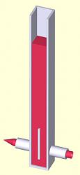
Because the mathematical description is the same, it is possible to visualize heat transport as a fluid transport:
Attachment 35328
In this drawing - limited by the capabilities of my CAD program - red stands for a fluid being pumped into a vessel (white) that is open at the top. Inflow and outflow pipes are separated by a baffle (also white) so that any fluid momentum is broken up and need not be considered. Under these circumstances, the total volume of fluid in the vessel may be taken as a representation of the heat inputted into the furnace, and the height of the fluid column as its temperature.
That is the global picture, and it assumes that heat (and fluid) travels everywhere at infinite speed. This is, of course, not true. The furnace walls act as insulators, to slow down the flow of heat and that needs to be accounted for.
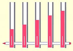
We do this by representing the furnace not as a single vessel, but many vessels connected in series parallel, and the limited travel speed of heat / fluid by a suitable small diameter of the inflow / outflow pipes:
Attachment 35329
This picture represents a cross-section through a furnace wall, and because the connecting pipes are suitably small, friction inside the pipes degrades the pressure available to uphold the length of the columns (the temperature) for each component vessel.
Third: Under this heading belongs the expansion of what has been said so far into three dimensions. This I will leave unsaid for today, as I will leave unsaid
Fourth: Implications for the placement of heating wires and furnace bricks,
giving you opportunity to mull things over and discover for yourself some of the consequences of what I have written so far. After all, my objective is not to tell you how to do it, but to enable you to find out for yourself.


 LinkBack URL
 About LinkBacks


 Reply With Quote


Bookmarks