Free 186 More Best Homemade Tools eBook:  
Get tool plans

User Tag List

Page 1 of 4 1 2 3 4 LastLast
Results 1 to 10 of 36

Thread: Height gauge addition.

  1. #1
    Supporting Member tonyfoale's Avatar
    Join Date
    Nov 2016
    Location
    Spain
    Posts
    1,607
    Thanks
    721
    Thanked 2,706 Times in 726 Posts

    tonyfoale's Tools

    Height gauge addition.

    This is just a quickie post. This afternoon I needed to measure the height of some holes off a surface plate. The usual measuring jaw/scriber has a flat bottom and is about 6 mm wide. This is fine for measuring flat surfaces but is not suitable for narrow vertical slots or holes.
    I decided to stop my work and make a replacement measuring probe which I am sure will pay me many times over in time saved down the road.

    My scrap box offered up a piece of 4140 which was hiding the piece that I needed, a broken 3 mm carbide drill bit completed the BOM.
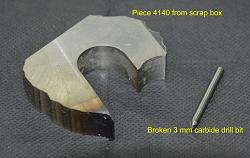
    Height gauge addition.-raw-materials.jpg Height gauge addition.-hidden-shape.jpg Click on thumbnails for full size images.
    On the left are the materials and on the right we see the piece hiding in the block (never throw out even the most useless looking scrap).
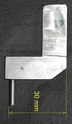
    Height gauge addition.-finished-thing.jpg Height gauge addition.-old-new.jpg
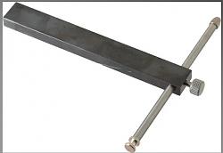
    Here is the result of half an hour's marking and milling compared with the original scriber.

    I wanted to position the bottom of the probe/stylus (I don't know what else to call it) such that it was the same distance down from the top reference surface as the original so that I could rely on the stock measuring scale. The original was 30 mm from the top surface to the underside of the scriber. To ensure this I initially drilled the hole centre, for the carbide drill bit, at 28.75 mm (30.25 - 1.5 = 28.75 mm. 1.5 is the stylus radius) down from the top surface. 30.25 mm instead of the final 30 mm to allow for any inaccuracy in positioning the hole. Then with the stylus pressed home I clamped the whole thing into the height gauge and used it to measure the height of a 10 mm gauge block. The vernier showed it to be 10.24 mm. I then milled another 0.24 mm off the top surface and retested. It was spot on as far as the vernier resolution could measure.

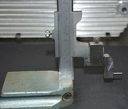
    Height gauge addition.-ready-go.jpg
    Ready to go.

    Height gauge addition.-use-01.jpg Height gauge addition.-use-02.jpg
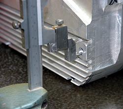
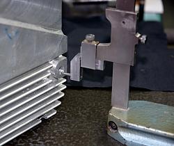
    Showing a typical application which the stock measuring jaw/scriber has trouble with. The new stylus has some material underneath it which prevents the stylus reading down to zero, the minimum is 3.5 mm but that is unlikely to be a problem for its intended and expected use.
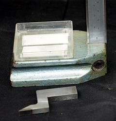
    Height gauge addition.-box-01.jpg Height gauge addition.-box-02.jpg
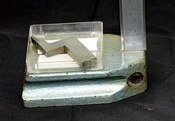
    Final touch. I used double sided sticky tape to fix a plastic box to the height gauge base to store the part not in use. A minor thing to do but of great importance to avoid losing a vital piece.

    A simple device, which I now wish that I had made decades ago. It wouldn't surprise me if similar probes are available commercially and/or home built by others, but I have not looked. I needed it there and then and making it was quicker than searching the net, ordering one and waiting for delivery.

    186 More Best Homemade Tools eBook

  2. The Following 17 Users Say Thank You to tonyfoale For This Useful Post:

    asterix (May 7, 2021), bimmer1980 (Nov 6, 2018), dekeros (Nov 11, 2018), dgbreggin (Aug 22, 2022), Frank S (Nov 3, 2018), freddo4 (Aug 2, 2022), Jon (Nov 5, 2018), LMMasterMariner (Nov 6, 2018), metric_taper (Nov 5, 2018), Miloslav (Dec 17, 2018), olderdan (Nov 4, 2018), PJs (Nov 6, 2018), rossbotics (Nov 4, 2018), Saltfever (Aug 7, 2022), Tonyg (Aug 3, 2022), Toolmaker51 (Mar 17, 2019), zarembak (Nov 5, 2018)

  3. #2
    Supporting Member tonyfoale's Avatar
    Join Date
    Nov 2016
    Location
    Spain
    Posts
    1,607
    Thanks
    721
    Thanked 2,706 Times in 726 Posts

    tonyfoale's Tools
    In a spare moment on the net I searched for "height gauge accessories" and much to my surprise I found nothing like the piece in the above post. However, I did find this cone based hole centre finder.

    Height gauge addition.-cone-1.jpg click thumbnail for full size image.

    It looks like it could be useful but it relies on the hole entrance being in good condition, which is not always the case. I think that I'll make one anyway but I'll use a shallower angle on the point.

    Another accessory that I found was for using a height gauge as a depth gauge. I'll definitely make one of these. I have been doing some reverse engineering lately and that will come in very handy.

    Height gauge addition.-depthattachment.jpg

    2,000+ Tool Plans

  4. The Following 2 Users Say Thank You to tonyfoale For This Useful Post:

    olderdan (Nov 6, 2018), Seedtick (Nov 5, 2018)

  5. #3
    Supporting Member Toolmaker51's Avatar
    Join Date
    Feb 2016
    Location
    Midwest USA
    Posts
    5,334
    Thanks
    7,044
    Thanked 3,011 Times in 1,900 Posts

    Toolmaker51's Tools
    A solid cone isn't bad as a center finder, but they don't have much 'feel' to ascertain contact with 100% of a hole in both axes. Mitutoyo's [and likely copies] is a pivoting flat arrow on a back plate, and scriber sized arm for height gauge. A fine lever-arm marks the arrow center, indicating a central location to corresponding line on back plate. Best feature is that precise vertical center isn't crucial, but works best on un-chamfered bores.
    It's not a scriber, only used to interpret relative position from a reference you establish. Simple as scribing line known height above surface plate, and positioning arrow at the line. A drill bushing atop a 1-2-3 block works for higher precision, from easily calculated center.

    It was designed and patented by a resident of Long Beach, Ca.
    https://www.google.com/search?q=mitu...aDn7A-z8lZuqM:
    Sincerely,
    Toolmaker51
    ...we'll learn more by wandering than searching...

  6. The Following 2 Users Say Thank You to Toolmaker51 For This Useful Post:

    olderdan (Nov 6, 2018), PJs (Nov 6, 2018)

  7. #4
    Supporting Member rossbotics's Avatar
    Join Date
    Dec 2013
    Location
    Florida
    Posts
    731
    Thanks
    1,019
    Thanked 1,684 Times in 404 Posts

    rossbotics's Tools
    I can see where that little creature would come in handy

    Doug
    Comments are always welcome
    Doug

    Subscribe to my you tube channel

    https://www.youtube.com/channel/UCDD..._as=subscriber


    Tool Plans for Sale by rossbotics


  8. #5
    Content Editor
    Supporting Member
    DIYer's Avatar
    Join Date
    Aug 2013
    Posts
    3,055
    Thanks
    793
    Thanked 1,888 Times in 1,683 Posts


    Thanks tonyfoale! We've added your Height Gauge Modification to our Measuring and Marking category,
    as well as to your builder page: tonyfoale's Homemade Tools. Your receipt:


  9. #6
    Supporting Member tonyfoale's Avatar
    Join Date
    Nov 2016
    Location
    Spain
    Posts
    1,607
    Thanks
    721
    Thanked 2,706 Times in 726 Posts

    tonyfoale's Tools
    Quote Originally Posted by tonyfoale View Post

    Another accessory that I found was for using a height gauge as a depth gauge. I'll definitely make one of these. I have been doing some reverse engineering lately and that will come in very handy.

    Click image for larger version. 

Name:	DepthAttachment.jpg 
Views:	344 
Size:	23.4 KB 
ID:	26217
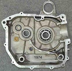
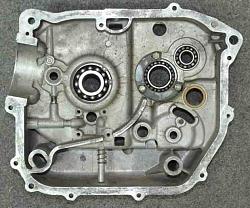
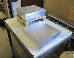
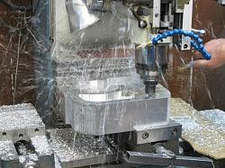
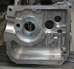
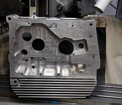
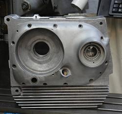
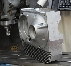
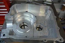
    I made a similar device, but instead of the clamping screw on a straight rod I used a threaded rod with a lock nut. This makes for an easy way to get a precise reference position. It has proved to be invaluable over the past few days for the reverse engineering that I have been doing. Motorcycle crank and gear cases with a view to making modified version out of solid 6061.

    Height gauge addition.-crankcases010.jpg Height gauge addition.-crankcases011.jpg Click thumbnails for full size images.
    Originals.

    Height gauge addition.-where2start.jpg Height gauge addition.-rainingswarf.jpg
    New ones.

  10. The Following 3 Users Say Thank You to tonyfoale For This Useful Post:

    Jon (Nov 9, 2018), olderdan (Nov 9, 2018), Toolmaker51 (Nov 9, 2018)

  11. #7
    Supporting Member olderdan's Avatar
    Join Date
    Jun 2016
    Posts
    793
    Thanks
    1,463
    Thanked 1,585 Times in 470 Posts

    olderdan's Tools
    Tony
    I know this thread is about measuring but the new engine casing project you posted looks really interesting. Have you increased engine performance over the years to a point the originals are over stressed or maybe stiffer/slimmer ones with your own crank for higher RPM. I hope we get to see the finished ones.
    Regards
    Alan

  12. #8
    Supporting Member tonyfoale's Avatar
    Join Date
    Nov 2016
    Location
    Spain
    Posts
    1,607
    Thanks
    721
    Thanked 2,706 Times in 726 Posts

    tonyfoale's Tools
    Quote Originally Posted by olderdan View Post
    Tony
    I know this thread is about measuring but the new engine casing project you posted looks really interesting. Have you increased engine performance over the years to a point the originals are over stressed or maybe stiffer/slimmer ones with your own crank for higher RPM. I hope we get to see the finished ones.
    Alan,

    There are several reasons for the new cases but the principal one is to be able to accommodate a larger bore. There is a limit to the bore size in the crankcase mouth before running into the stud holes. 78 mm is about the maximum without making the cast iron liner too thin as well. With the new cases I'll be able to go to 92 mm at a push. The new cases will also be a bit heavier to increase rigidity. Stiffness is all important in the bottom end and I'll also be using a short stroke one piece crankshaft in place of the stock built up shaft.
    With the new cases and crankshaft I should have a bullet proof bottom end which will support whatever power I get from the top end.

    I'll take some pix of the current progress and post some here in the next day or two.
    An interesting aspect is how I plan to ensure alignment of the bearing bores in the two halves. Both halves have to be bored separately for several reasons. if I get a moment i'll write that up or maybe make a video.

  13. The Following User Says Thank You to tonyfoale For This Useful Post:

    Toolmaker51 (Nov 9, 2018)

  14. #9
    Supporting Member Toolmaker51's Avatar
    Join Date
    Feb 2016
    Location
    Midwest USA
    Posts
    5,334
    Thanks
    7,044
    Thanked 3,011 Times in 1,900 Posts

    Toolmaker51's Tools
    I'm somewhat floored by urge to make a billet crankcase; but motivations are perfectly logical. I imagine it'll be undertaken via CNC? Billet cases have perfection written all over them, right down to modifying drainage tracts, fixturing pads, ultra clean fillet & radii, ad infinitum. Fixture pads would aid line boring process with permanent datum. Not to mention increased strength from cast 356 to rolled 6061. If you've ever worked 7075 though, it may prove even more superior, and the finish is spectacular!
    Sincerely,
    Toolmaker51
    ...we'll learn more by wandering than searching...

  15. #10
    Supporting Member tonyfoale's Avatar
    Join Date
    Nov 2016
    Location
    Spain
    Posts
    1,607
    Thanks
    721
    Thanked 2,706 Times in 726 Posts

    tonyfoale's Tools
    TM51.
    The machining will be a mixture of manual and CNC. Most but not all roughing will be done manually. Finishing of the sections where the G-code can be written manually and those sections which lend themselves to using some G-code generation software that I have written will be done with CNC, the rest manually. I have no intention of spending the time to make CAD drawings in order to do 3D profiling of the undulating surfaces. Those sections will be redesigned to have fewer flat levels. The critical bearing bores will be made with a nice Narex boring head which I picked up a couple of years back.

    Alan
    here are a few pix. of progress to date as per your request. The original case halves weigh 4.1 and 4.2 kg. One of the new ones still weighs 8.5 kg and the other 10.5 kg so I still have a lot of swarf to make. I spent all morning machining and was most disappointed to have only removed another 1.2 kg.

    Height gauge addition.-dsc_0578a.jpg Height gauge addition.-dsc_0581a.jpg Click to see full size images
    RHS cases from inside and outside. This is the most complex half case.

    Height gauge addition.-dsc_0582a.jpg Height gauge addition.-dsc_0583a.jpg
    RHS with stock cover dowelled and bolted in place.

    Height gauge addition.-dsc_0561a.jpg
    Inside of LHS case. Simpler than the RHS.

  16. The Following 3 Users Say Thank You to tonyfoale For This Useful Post:

    HUMARIA (Mar 18, 2019), olderdan (Nov 11, 2018), Toolmaker51 (Nov 10, 2018)

Thread Information

Users Browsing this Thread

There are currently 1 users browsing this thread. (0 members and 1 guests)

Tags for this Thread

Bookmarks

Posting Permissions

  • You may not post new threads
  • You may not post replies
  • You may not post attachments
  • You may not edit your posts
  •