DIY Vise with transverse position adjustment and movable claws. Clean design.


Carnel (Aug 4, 2020), Jon (Aug 2, 2020), LMMasterMariner (Aug 3, 2020), mwmkravchenko (Aug 3, 2020), Saltfever (Aug 7, 2020), Tule (Aug 6, 2020)
LMMasterMariner (Aug 3, 2020)
Very nice machining work but I'm a bit concerned about the method of locking the three jaws to the base plate. If the pressure screw is strong-armed, will the jaws move? Even a few thousandths of movement would matter in precision machining operations.
If the pressure screw were longer than the 'fixed' jaw and the plate through which the screw is threaded could be permanently affixed to the base. Of course, this would make it look much more like a conventional machinist's vise. Perhaps it would help if you explained why you designed your vise the way you did.
There are a couple of modifications you could make to improve the utility of your design...
Put steps in the two jaws that grip the work so thin stock could be held near the top of the jaws without the need to use parallels.
Put elevated steps on the outboard ends of both the gripping jaws so stock larger than the current jaw opening could be accommodated.
Space the hold down screws in the base so the vise can be mounted parallel to the T-slots as well as perpendicular as shown in the video.
Add a spinner to the tightening screw so the pusher can be snugged up with the fingers before tightening with the Allen wrench. Alternatively, use a hex head screw so a small box wrench can be used.
---
Regards, Marv
Failure is just success in progress
That looks about right - Mediocrates
machining 4 all (Aug 2, 2020)
Thanks for the interest mklotz! Responding to your comments:
- It is not necessary to tighten the fixing screws so much to obtain a good fixation of the claws. The dovetail allows a very effective fixation of the claws on the guide. When I perform machining of precision, usually my machining depth is less in finishing operations, so the claws are not as requested.
- I also tried to make a different vise model. Nothing against it, but have you noticed that most people who post videos making vises use a vise in their manufacture? As I don't have a vise (I now have this one) I used the resources I have (a mini lathe, a milling machine and a drill).
- The system has been designed in this way to allow the claws to move freely. From mechanics, we know that Torque = Force x Distance. Applying a moderate force of 8 kg to the key (in this case Allen M12) which is 110 mm long, a torque of approximately 9.0 N.m (approximately 6.7 Lb.ft). This value is more than enough to hold the components in place.
- Each claw is 30 mm wide, which gives approximately a contact area equal to 2.52e-6 m2 between claws and guide. From mechanics we know that Pressure = Force / Area. If we apply a force moderate equal to 8.0 kg per screw, we will have a pressure of approximately 63.5 MPa (approximately 9200 Psi) acting on each contact between grapple and guide. This pressure, for a hobysta vise, is more than enough to perform small tasks...
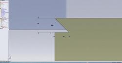
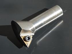
- For example, the metal plate that appears in photo 1 and photo 2 was manufactured in this vise. The machining was smooth, without any problem.
- I will definitely machine channels in the jaws to fix fine materials, so I don't have to use parallel shims. However, I will machine and temper two shims where I intend to make these channels.
- I will still perform the machining of the vise base, where I will place two discs so that I can perform rotation, allowing angular machining.
- I forgot to mention, I bought the material for manufacture in the scrap. The total value of the project (material and screws) was an incredible 6 dollars (except my labor, which is part of the fun). The total manufacturing time was approximately 7 hours.
I don't know if I answered everything that you kindly commented, but that's what I thought when executing this project. Thanks again for the considerations!
Last edited by machining 4 all; Aug 2, 2020 at 01:14 PM.
Thanks machining 4 all! We've added your Vise to our Vises category,
as well as to your builder page: machining 4 all's Homemade Tools. Your receipt:
New plans added on 11/20: Click here for 2,589 plans for homemade tools.
machining 4 all (Aug 3, 2020)
There is elegance in simplicity! The modular nature of your design has given me some great ideas. Replaceable jaws can be easily changed. A feature can be machined on one side of the jaw and then turned around as needed. I would certainly have a vertical “V” grove in the middle of a jaw for round stock as wells as a horizontal V grove in one of the gripping jaws. Additional jaws with special features can be machined and added as needed. My only concern is the one feature that makes the vise so adaptable. A dovetail concentrates stress and a failure will occur over time. I will try to create a radius at the bottom of my dovetails.
Thank you for sharing your idea. All the best.
PS: One set of vise jaws could have dovetails. You machine a matching dovetail on your stock and have tremendous gripping strength with as little as 0.060" (1.5mm) stock. When you have finish machined the top it is turned over and the small amount of stock is removed.

Last edited by Saltfever; Aug 7, 2020 at 01:43 AM. Reason: Insert pic
machining 4 all (Aug 7, 2020)
Saltfever, thanks for the comments! It is good to know that my project was able to dispel the creativity of other colleagues! The dovetail is present in practically all industrial equipment, I didn't invent anything, I just used the concept. And if you don't have the tool to machine, you can make it yourself! To round the edges, just use a tool with a higher tip ratio and you minimize the problem of stress concentration!


Last edited by machining 4 all; Aug 7, 2020 at 12:40 PM.
There are currently 1 users browsing this thread. (0 members and 1 guests)
Bookmarks