Looks like a Nice, clean winding job. Is that Teflon around the outside? The EL34's look great...Nice find! Thanks for the update.
~PJ


rendoman (Sep 21, 2016)
Around the outside I used a strong paper used for electric motor, should be mylar paper according to old man who gave it to me. Very rigid and in various thickness, I used 0,2mm. He gave me also a very nice mylar scotch tape, close to perfection to keep winding in position. Unfortunately calculations foresaw slightly different values, I got maybe a bit low inductance and resistence as anode choke. Some manufacturer has anode choke of high impedence (80\100H for 10-20hz use), I don't need low cutoff frequency, but I got some doubts about this. The good thing is that I got space in bobbin, I can wind maybe 5x of actual turns, and maybe this time, with lathe, luckily is only an inductorobviously I will try to do by hand
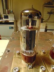
This El34 tube are made for Langrex, a uk company of tubes and electronic parts. For sure made in Cina by Shuguang factory, quad matched. Imho this production is a "good selection" of el34, maybe matched in factory during test. I would like to think so. Even if they were only fables, 15 euro shipped each tube is a good price. In my city shops I've seen similar price range tubes ( chinese, JJ, elettroharmonix ) from 22 to 45 each, even on ebay price are good.
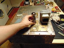
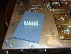
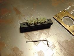
I try new layout, I'm trying to make a good use space. For final version, no potentiometer, no volume, and switches in the back, in order to not keep around half meter of 6 cables for power supply. I have to find a good amperometer and maybe a voltmeter till 2kv, not easy to find, unfortunately! This evening I made a couple of support for power supply and Hv unit, to Mount close to sockets.
I changed Gu50 position because heat, and thinking the worst scenario, the replacement of final oscillator tube with one of a higher class (Gk71 - 813 for example). I really want to keep gu50 in circuit, because it's good, but you never know... better to get hands on
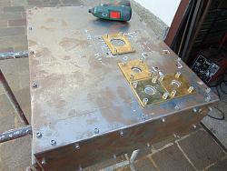
I'm not sure if it's better to use milling machine to open large drill on thin steel, or maybe use the oxy torch, for sure a fast work!

Nice the old guy gave you some paper and Mylar tape. The paper, if made for xformers will be fine with a layer of tape over it. I know you are winding this yourself and it's a pain, but you can change your inductance with the gauge wire...but still depends on the frame quality, laminations & permeation you have. 80/100H does seem high but not sure in this case either.
Really good prices on the EL34's especially if they are Matched...wouldn't count on them being perfectly match but close would be great for this stage.
Glad you are shortening your wire runs it should really help in the isolation. Perhaps you could run the low voltage stuff on one side of the frame and the higher on the other. What is the amp meter for? For the amp meter you can always use an external shunt with an MA meter. A 2kv voltmeter is a bit more tricky to find but again you could build a small external voltage divider circuit...in both cases you'll need to rescale the meters and they will lose some linearity.
I'd think the mill would be better for the larger holes, but you need to work on the cutting geometry of the boring setup you have...although you might find a hole saw (~$15-20) the right size and go slow (peck it) with lube. Give yourself plenty of clearance to the hole in your brass plates for wiring and isolation. To me the torch would mess up your pretty work so far and need a lot of clean up.
Good progress! Thanks ~PJ
‘‘Always do right. This will gratify some people and astonish the rest.’’
Mark Twain
rendoman (Sep 22, 2016)
I'm trying to understand how plate choke runs in circuit, I read many things, but this site puts confusion in ny head
Magnequest Tech: All choked up on Grid and Anode Chokes
Reattanza induttiva online fast calculator
My need is a 100ma coil , for a 3,5k load in pentode mode el 34. (15 kohm internal resistence for el34 in pentode),
For sure, normal audio amplifier should reach 20 hz min frequency, for normal operation. My plasma will be start from 1000hz, ideal starting frequency, maybe it can fall to 500hz, but horn becomes big
Magnequest advice is to keep 8 times internal resistence of tube, talking about output transformer, and in the middle of page the formula of reactance. I have trouble understanding this site because data imho are confused
Magnequest Products - MQ Iron Listing/Pricing
Let's take for example BAC80 model, rated 80ma, 50H , 325ohm resistence (same current of my amplifier)
Formula gives for 50H and 20hz freq, 6280 ohm of reactance , that is +/- double than the recommended 3k load for pentode, but still usable as load for the same amplifier.
According to site, why to 8x the internal resistence of tube? can be a good rule for a low resistence tube, but not for a pentode imho.
Calculaton for my inductor, 3H , at 320hz give me a reactance of 6K, that's double of normal loading of my tube. In theory, if I filter the imput with and high pass with this value, everything should run ok, or I overlooked something?
I think I'll find out soon
Ps: I used oxy torch, and file, because frame was to big to lock on milling machine
Ps2: I'm thinking about data
- 8x internal resistence = inductance es: 8x 15K = 120H (at 20hz)
- my inductor is 3H, reach 15kohm of reactance at 750hz
- if I want to lower frequency, keeping 15Kohm minum, I have to increase inductance at 7H for 320hz for example, or 25H for 100hz.
my question is: why 8x the internal resistence?
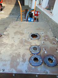
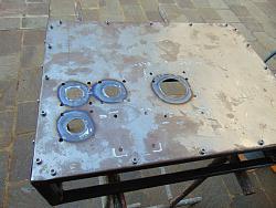
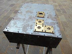
Last edited by rendoman; Sep 23, 2016 at 02:27 PM. Reason: new pictures and new thoughts
Stephano, I feel like I'm back peddling here at this point again. First I don't know if you are changing the EL34 circuit to a single class A or push/pull double...but you said pentode mode so that helps in looking at the curves on the cut sheet. Second you never said what your differential g1 voltage is. Third in your calcs I don't know where you got the 325Hz from but if you put the numbers in the calculator you get 6K-XL...yes. Yes the Ra is 15K for pentode mode (see below).
The Manquest Tech article is pretty dry reading and a bit jumbled IMHO. It does clearly state things in a way to sell their products and why. Basically your coil looks to be a low leakage CMC but the cover will help with shielding...but again shooting in the dark because of conductor size/type and core type. In your BAC80 example you say that it is double the 3K load...but on the cutsheet page D2 under a "distributed load grid tapping 43%" it does show 6K in Push Pull and I am Assuming that is an XL value. @¿@ Have NO idea where or why they came up with the ">=8H per kohm of R_plate measured at < 1/10,000 of rated output power". Especially with the <1/10k rated output power. They must have some serious equipment to be able to measure this and or it may be some Physics/EE thing I forgot after 30 years. The site is definitely for Hi End audio file components though.
Honestly, I can't say if you missed something or not so All I can do at this point is sit back and
I get it about the torch/mill size!
~PJ
‘‘Always do right. This will gratify some people and astonish the rest.’’
Mark Twain
rendoman (Sep 23, 2016)
Sorry, I thought I wrote in previous posts
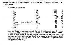
El34, amplifier part, for now follows datasheet specification, then :
anode voltage 300, grid 2 300v, Rk 190ohm, Ia 80ma, Ig2 13ma, 11w power output with 8.2v g1 load 3,5k
I'm also thinking about second working point, for same output , with different load.
anode voltage 250, grid 2 250v, Rk 106ohm, Ia 100ma, Ig2 15ma, 11w power output with 8v g1 load 2k
https://frank.pocnet.net/sheets/129/e/EL34.pdf
Is nothing more than the official data. I will modify the circuit if necessary, but I think it's a good starting point.
Forgot frequency, numbers and formulas for now. I see that in similar amplifier circuit, when it's used an anode choke instead of an output transformer, values of inductance change for some reason between the 2 parts.
Compared to normal output transformer (3.5k load , 15H), inductance numeric value of an anode choke for the same load is maybe 50H or more. I tried to explain to myself with the formula of inductive reactance of coil, observing the products and the results I concluded that:
-For an "X" tube with "Y" internal resistence, anode choke inductance should be chosen 8 times the internal resistence
putting in calculator 15k x 8 = 120H , and 20 hz frequency the result of reactance is 15kohm, same as internal res of tube.
I deduced that for normal hi-end audio (range freq 20hz - 20khz typically) (8x is the "rule" in order to make a good anode choke for "X" tube.
-second step, reactance formula is valid at a certain frequency. I don't need 20hz in a tweeter, range will be 1-20khz for example.
It's important that the low-end frequency of my inductor (anode choke) should have a reactance equal to internal resistance of tube.
My 3H coil for example, has a reactance of 15Kohm at 750hz. Taking the lowest frequency value for 15k, this coil should be good for an amplifier that sounds from 750hz to 20khz.
Using formula, I can keep 15k (I need this value fixed), I can also lower the frequency, at price of raising inductance of coil, then for example if I want my amplifier sounds from 100hz I will need 25H coil in order to have 15k reactance.
I think you're right about commercial sites, in particular this magnequest is pretty dry of info! I only tried to use this info to make a sense. Unfortunately even books have not satisfied my thirst for knowledge
One thing is sure! this post is pretty useful for my to keep record of all modifications done
I hope this page could be both of leisure and good reading even to the forum members
PJs (Sep 23, 2016)
A good evening with a friend and some bourbon
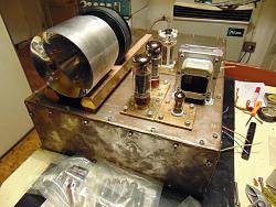
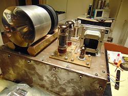
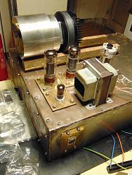
I'm going to put parts on frame, and trying to imagine a new plasma tweeter. Position of sockets is good, I'm thinking about powersupply transformers, switches and other parts. I think I will buy a single 500va toroid and put a couple of relays in order to cut high voltage and maybe filaments.
The 2 long hexagonal brass are only for picture, although I like them cut short.
Step by step this monster is on! I hope!
PJs (Sep 27, 2016)
PJs (Oct 5, 2016)
HI all
... that's not a good evening, unfortunately!
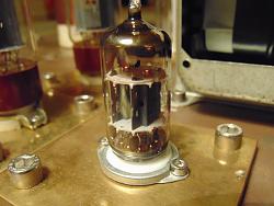
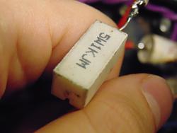
I've not seen that a crucial ceramic resistor broke its rheophore, leaving uncovered a part of the circuit.
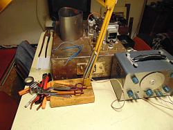
Results: melted a mundorf capacitor, the outside of another cap, and damaged a resistor in only 10 seconds. There are also good news, flame is pretty big with only 50ma, imperturbable to environment, with or without semi-faraday gage. Shielded frame seems pretty good.
Autofire is more rapid than in the past.
Base is good, now I have to re-start tuning
PJs (Oct 11, 2016)
Sounds like good progress! But maybe a "Bit under wattage" on the wire wound...and also way too close to other components. One thing about ceramic wire wound resistors is were the lead comes out of the ceramic. To much flexing of the lead and or too hot soldering close to the ceramic weakens the wire at the joint and they will break. They also make ceramic wire wounds encased in an aluminum heat sink you can mount to the chassis or a bracket.
For the foil cap you might try to find a replacement Spraque/Cornell "Orange Drop" epoxy resin type and can get them down to 3-5% if necessary. Pull the 100uf electrolytic and toss it...the bleeder hole is likely damaged from the excessive heat.
~PJ
‘‘Always do right. This will gratify some people and astonish the rest.’’
Mark Twain
There are currently 5 users browsing this thread. (0 members and 5 guests)
Bookmarks