Free 186 More Best Homemade Tools eBook:  
Get 2,500+ tool plans, full site access, and more.

User Tag List

Page 16 of 20 FirstFirst 1 2 3 4 5 6 7 8 9 10 11 12 13 14 15 16 17 18 19 20 LastLast
Results 151 to 160 of 198

Thread: Good advices for a newbie (threading tools lathe)

  1. #151
    PJs
    PJs is offline
    Supporting Member PJs's Avatar
    Join Date
    Sep 2014
    Location
    Northern CA
    Posts
    1,844
    Thanks
    8,431
    Thanked 1,129 Times in 725 Posts

    PJs's Tools
    From what I saw in the previous post, I would doubt you are pulling 500W (.5A @1KV) from 2, 40W tubes...otherwise they would be melting the plates, grids, filaments and likely the glass...and you will Ruin your nice porcelain socket! IMHO you are pushing the tubes way tooooooo hard from the Pics above. Keep in mind that with the plates glowing deep red you are giving of pretty good amounts of infra Red and some X-Rays...Not good! One thing about tubes is the more you push them, they begin to break down and become LESS Efficient, with a much shorter life span. Properly breaking in a tube will give you the best results and last, usually longer than the life spec.

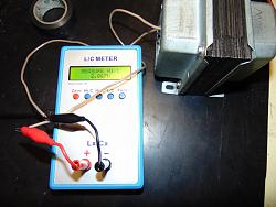
    As for the 100mhz (if it is accurate) it may be some harmonic you are seeing because of the ~30mhz oscillator and it may have other spurious emissions you are picking up from the surroundings and the way the table is laid out...not sure I trust that digital meter at those frequencies.

    I can see RF burns on the coil ceramic. It will be metalized and throw off your the whole kit and Kaboodle of frequency/mH/resistance at these frequencies. Might try cleaning it with Acetone but be careful of your wire...it'll take the coating off in a heartbeat.

    The flame definitely looks better shape and size.

    Honestly Stefano I liked it much more when you were working towards the goal of an audio plasma speaker with a custom cone. This is starting to feel like a 5KW tesla music modulator, not an Audiophile Plasma Speaker. It is fun to push the envelope sometimes but it is dangerous...even with what you are working on and do Not want to see you hurt, nor discourage you from reaching your original goal!

    Efficient, Efficient, Efficient, Efficient! Your Call!

    Till Then,
    ~PJ

    186 More Best Homemade Tools eBook
    ‘‘Always do right. This will gratify some people and astonish the rest.’’
    Mark Twain

  2. The Following User Says Thank You to PJs For This Useful Post:

    C-Bag (Jul 19, 2016)

  3. #152
    Supporting Member C-Bag's Avatar
    Join Date
    Aug 2015
    Location
    California, central coast
    Posts
    720
    Thanks
    689
    Thanked 879 Times in 471 Posts

    C-Bag's Tools
    Wow, u da man Wiz.......

    2,500+ Tool Plans

  4. The Following 2 Users Say Thank You to C-Bag For This Useful Post:

    PJs (Jul 19, 2016), rendoman (Jul 22, 2016)

  5. #153
    Supporting Member rendoman's Avatar
    Join Date
    Nov 2015
    Location
    Italy
    Posts
    435
    Thanks
    451
    Thanked 496 Times in 241 Posts

    rendoman's Tools
    Hi again!

    Pj your right, It's better I focus on audiophile plasma!
    But the more I experience, the more I realize that I know nothing about electronic
    Summing in few words: I'm experiencing different kind of circuit. With the precious support of digital scope, some softwares and some old papers I'm ironing out the kinks.

    The reason why I'm chianging so many parts, working points and circuit is that I got really low volume, not enough to match a good speaker.
    I tried to double oscillator in order to have a better flame, running at low, mid, high, and over range just to know how circuit works. At full power of double oscillator, another amperometer connected showed something less 0,5A at 950v with load, something more than 400w. Thanks russians this tube is made in hell, with nickel - zirconium plate is strong enough to survive these test lossless.
    It's clear that I can't run during normal use of tweeter at red plate, and maybe it's not even necessary. I saw that 1cm flame (minimum now with 60v dc on g2) should be enough.

    Good thing is that from oscillator I think I took everything I could, well tuned.
    Bad thing is that Whole rearguard is inefficient. I'm focusing on amplifier, I Did different setup:

    - Pcl 82 triode + pentode 1.6 / 3 watt

    - 6sn7 + el84 2.5w undistorted, 5.5 w max (I think I will make a new amp for my horns with this setup, it's really better than my ecl82)

    - 6sn7 + gu50 at low voltage (300v - 160ma), I tried both single ended driver and srpp, completely unuseful!
    Poor anode amplitude, poor power output.
    I tried this night using a pcl82 in triode to drive this tube, 3,5w undistorted, or with both eyes closed some 7w... huge power consumption for nothing.
    I think this tube need more voltage and powerful driving, I'm even more convinced on el34, with good full datasheet, not the toilet paper of gu50.

    I got a strange feeling about modulator el84, imho this part of circuit is making a big mess. Don't know why, actually, but I think there is something strange that blocks audio power. I'm studing a better modulator, maybe high level mod?


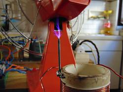
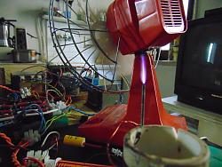
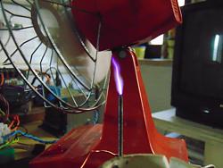
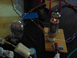
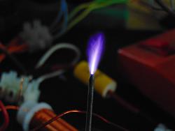
    nice picture of a plasma acting like a tesla coil, unfortunately caused by some ground issue
    Good advices for a newbie (threading tools lathe)-13738262_10209840186664055_3788649250886931548_o.jpg

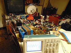
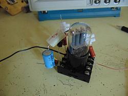
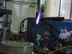
    soft mess on the table
    Good advices for a newbie (threading tools lathe)-dsc00948_1600x1200.jpg

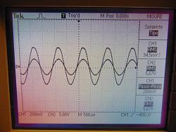
    Output of gu50 amp, pcl82 driver stage is strong
    Good advices for a newbie (threading tools lathe)-dsc00949_1600x1200.jpg

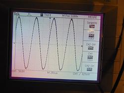
    Gu50 anode amplitude
    Good advices for a newbie (threading tools lathe)-dsc00950_1600x1200.jpg

    Little monster, with no hum
    Good advices for a newbie (threading tools lathe)-13725070_10209840186704056_9194772968928015790_o.jpg

  6. The Following 2 Users Say Thank You to rendoman For This Useful Post:

    C-Bag (Jul 23, 2016), PJs (Jul 23, 2016)

  7. #154
    PJs
    PJs is offline
    Supporting Member PJs's Avatar
    Join Date
    Sep 2014
    Location
    Northern CA
    Posts
    1,844
    Thanks
    8,431
    Thanked 1,129 Times in 725 Posts

    PJs's Tools
    Thanks for the update Stefano. I get it that you are somewhat of a novice with the circuits but you have achieved success with what you had set up imho. The "Loud enough" is hard to quantify for me and still think you have some mismatch components in the circuit. Here are a few more thoughts from an old fart that hasn't done any of this stuff in 3 decades.

    Old circuit.
    1. As I mentioned in our PM's the 22nf cap between the output of the PLC82 and the input of the EL84 is WAY too small. Try a .01uf and move up to maybe a 10uf or bigger. There also needs to be a pull down resistor....see Pg. L of the data sheet. They show a 35uf and 5.6k for the output circuit in the diagram of the curve chart. Also on the EL84 that R network from the plate to ground and G1 with the 180k, 100k pot, 22k and the 1k off the center of the pot seems like it will kill what you are getting from the PLC82...especially with that 22nf in there, particularly your higher frequencies. You want to hold your G2 (EL84) to ~250v @ ~10ma and the 180Ω seems about right. Your output on the PLC82 needs to be about -7.3V at G1 on the EL84 but it feels like the cap and R network are giving you something else.

    2. I still don't understand how the cathode (EL84) to G2 (GU50) works to drive the gu50 as a modulator with G1 being your oscillator. Typically you would use an output circuit between Plate and ground to drive the GU50 (G2) as a modulator carried by the oscillator. This also may be some of the issues you are seeing with the modulator circuit...its basically open and dissipating its output through the R network above, to Ground. According to the "toilet paper" G2 on the Gu50 should be ~250V and you are pulling it to ground through the cathode.

    New circuit...
    I like the idea of the 6sn7 feeding a push pull pair of EL34's. That would give you 25W available if necessary into the GU50 as a modulator...if you still want to use it as an oscillator/output. Honestly, I think 40-50W is plenty with your Horn, if it is achieved cleanly between each circuit. I would build your 6sn7 circuit drive it with the Analog Frequency Gen. and dial it in until you get clean output at around 5W. Then build your EL34 circuit to match the output of the 6sn7...and test them with the Generator till you get clean output at around 15-20 watts...more than enough to drive G2 of the Gu50...probably going to need to tone it down and not cause distortions on the output of the plasma.

    I haven't spent a lot of time on this new circuit but those are good solid tubes for your application...and good sheets/circuits available.

    S'all I got for now. Good Luck!!

    ~PJ
    ‘‘Always do right. This will gratify some people and astonish the rest.’’
    Mark Twain

  8. The Following 2 Users Say Thank You to PJs For This Useful Post:

    C-Bag (Jul 24, 2016), rendoman (Jul 24, 2016)

  9. #155
    Supporting Member rendoman's Avatar
    Join Date
    Nov 2015
    Location
    Italy
    Posts
    435
    Thanks
    451
    Thanked 496 Times in 241 Posts

    rendoman's Tools
    Hi all
    This post is really useful as a diary for me, all the changes I made are here! And it's Always a pleasure to show you some nice picture.

    It's difficult but I'm trying to follow PJs way, more method and focus on problems.
    Few words about last changes, I tried to focus on power part of circuit. There was some issue related to a wrong choice of tube, that's why now I got 2 gu50, one as mod and one oscillator.
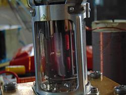
    Things are really better now, no more red grids, light red plate with full output and lower consuption of current.

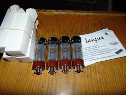
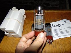
    I'm waiting a couple of el34 tubes, I have to raise power and amplitude from amplifier now, and maybe I will be ok in principle, last adjustments will be done with final frame.

    Sound is loud enough, even without horn. Combustion chamber + horn will be necessary in order to erase ozone.
    See you on the next episode


    Good advices for a newbie (threading tools lathe)-dsc00961_1600x1200.jpg Good advices for a newbie (threading tools lathe)-dsc00963_1600x1200.jpg Good advices for a newbie (threading tools lathe)-dsc00967_1600x1200.jpgGood advices for a newbie (threading tools lathe)-dsc00969_1600x1200.jpg Good advices for a newbie (threading tools lathe)-dsc00970_1600x1200.jpg Good advices for a newbie (threading tools lathe)-dsc00973_1600x1200.jpg
    Last edited by rendoman; Jul 28, 2016 at 08:38 PM. Reason: Forgot youtube link

  10. #156
    Supporting Member rendoman's Avatar
    Join Date
    Nov 2015
    Location
    Italy
    Posts
    435
    Thanks
    451
    Thanked 496 Times in 241 Posts

    rendoman's Tools
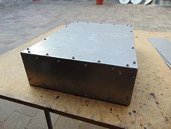
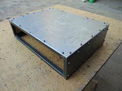
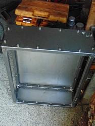
    New small update, after august
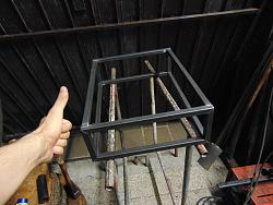
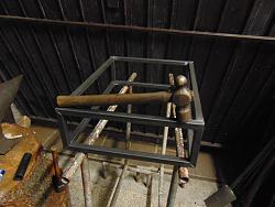
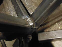
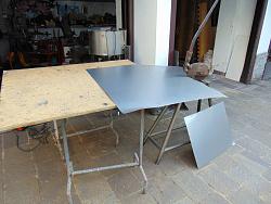
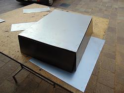
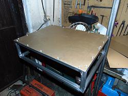
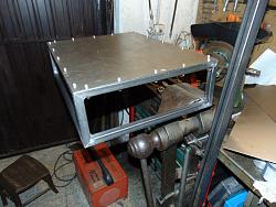
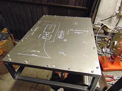
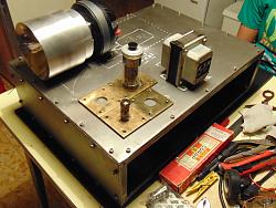
    I'm building a new frame, bigger than the old one. The reason is that I need more space for tubes and rest of circuit. I'm also converting the old frame to fit my tube amp, keeping brass panels and general layout.
    This time I will cover the tubular frame with steel plate.
    I also rebuilt circuit in order to run el34 tube, I'm undecided with first gain stage, 6sn7 or ecc82 - 12au7, I got both of them and performance are close.
    I hope next week I will receive new tubes and sockets!
    Let's start again the project!

    Good advices for a newbie (threading tools lathe)-dsc01176_1600x1200.jpg Good advices for a newbie (threading tools lathe)-dsc01179_1600x1200.jpg Good advices for a newbie (threading tools lathe)-dsc01181_1600x1200.jpg

  11. The Following User Says Thank You to rendoman For This Useful Post:

    PJs (Sep 9, 2016)

  12. #157
    PJs
    PJs is offline
    Supporting Member PJs's Avatar
    Join Date
    Sep 2014
    Location
    Northern CA
    Posts
    1,844
    Thanks
    8,431
    Thanked 1,129 Times in 725 Posts

    PJs's Tools
    Nice looking frame Stefano. Figured you were pondering where to take this great build! Looking forward to whatever progress you make on it. All good choices for the first stage just depends on what filament supply you have most of, I think.

    Keep on Keepin' On...Thanks for sharing, ~PJ
    ‘‘Always do right. This will gratify some people and astonish the rest.’’
    Mark Twain

  13. The Following User Says Thank You to PJs For This Useful Post:

    rendoman (Sep 10, 2016)

  14. #158
    Supporting Member rendoman's Avatar
    Join Date
    Nov 2015
    Location
    Italy
    Posts
    435
    Thanks
    451
    Thanked 496 Times in 241 Posts

    rendoman's Tools
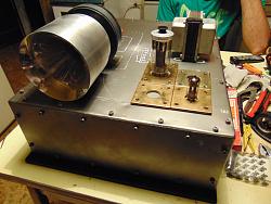
    I'm trying to study parts position, tube sockets grouped, output transformer close to el34 amp tube.
    A bigger horn compared to old one, because frequency range is increased. I will put separated gnd for circuit and frame.
    I want to braze with brass the edges of panels, just to give a better old - steampunk look, I'm not sure, that's only an idea!
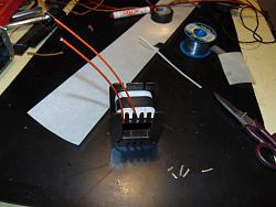
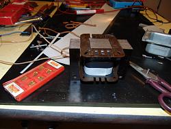
    I have to wind output transformer, dedicated with low inductance, in order to reach high freq. Lot of turns by hand.... infinite work

    I have to think about main coil, I got problem of heat and temperature. I have to find, or make a couple of support. Tin-lead melt at 180°C , with 5cm tungsten tip at full power I melt the welding in few seconds. A mechanical link is good, but I'm not sure Teflon can keep this temperature (even if tweeter will not run at full fire Always), and I don't know how to model ceramic... I Have to think about this problem

    Good advices for a newbie (threading tools lathe)-dsc01182_1600x1200.jpg Good advices for a newbie (threading tools lathe)-dsc01183_1600x1200.jpg Good advices for a newbie (threading tools lathe)-dsc01186_1600x1200.jpg

    Good advices for a newbie (threading tools lathe)-dsc01187_1600x1200.jpg Good advices for a newbie (threading tools lathe)-dsc01189_1600x1200.jpg Good advices for a newbie (threading tools lathe)-dsc01191_1600x1200.jpg

    Good advices for a newbie (threading tools lathe)-dsc01192_1600x1200.jpg Good advices for a newbie (threading tools lathe)-dsc01193_1600x1200.jpg Good advices for a newbie (threading tools lathe)-dsc01195_1600x1200.jpg

    Good advices for a newbie (threading tools lathe)-dsc01198_1600x1200.jpg Good advices for a newbie (threading tools lathe)-dsc01199_1600x1200.jpg

  15. The Following User Says Thank You to rendoman For This Useful Post:

    PJs (Sep 15, 2016)

  16. #159
    PJs
    PJs is offline
    Supporting Member PJs's Avatar
    Join Date
    Sep 2014
    Location
    Northern CA
    Posts
    1,844
    Thanks
    8,431
    Thanked 1,129 Times in 725 Posts

    PJs's Tools
    Looking Good Stefano. Layout is one of those things on a project like this that must take a lot into consideration like close coupling, isolation, grounding, spurious emissions, let alone all the mechanical's...etc. In this case the biggy is HV AC/RF to DC to Audio...and Ground planes. The other is porting thru a Faraday cage. What you are doing placing the actual component on the chassis is the best way to flush out the puzzle of this type. Take your time and go to that Zen place with it...eventually its cork will float.

    Did you measure these temps? Silver solder would work up to about 500Cº. My suggestion for the Tungsten electrode would be to make a mechanical connection. Maybe a double ended, machined brass ferrule with minimal (slip fit) for the tip and conductors and maybe 12-15mm diameter so you can put in 2 set screws (3-4mm?) for each end. One set screw (socket head dog point or cup, type not cone) would work probably, but 2 better @ 60º. The key would be to keep it small diameter as possible to keep the spurious emissions down in that area. As for a support maybe a rectangular block of PTFE if you have it...it's should be good up to about ~200Cº. Maybe 2 square porcelain standoffs with a smaller block between them for support¿ It would also depend if you will use the ozone isolation glass tube. Alignment to the cone and some kind of fine tune adjustment would help to dial it in.

    As for the coil, your porcelain tube can use a mechanical half cup type connection through the existing holes at each end and supported by some of that green stuff or UHMW blocks or a ring?? Good to ~200Cº...it should never get that hot...hopefully. Make sure to clean all the burns from it.

    Like the Steam Punk idea but don't let it dictate what it needs to be electronically.

    Thanks for the update! ~PJ
    Last edited by PJs; Sep 15, 2016 at 11:04 AM.
    ‘‘Always do right. This will gratify some people and astonish the rest.’’
    Mark Twain

  17. The Following User Says Thank You to PJs For This Useful Post:

    rendoman (Sep 15, 2016)

  18. #160
    Supporting Member rendoman's Avatar
    Join Date
    Nov 2015
    Location
    Italy
    Posts
    435
    Thanks
    451
    Thanked 496 Times in 241 Posts

    rendoman's Tools
    Thanks for the advice! I will think with fresh mind this time the layout!
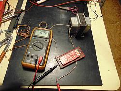
    I finished the output transformer - anode choke for audio amp inside plasma. 3,5K load, 100ma, high freq cutoff, low inductance and resistance, hope it will run good with el34 tube. I'm searching info about this type of loading (without a real load on secondary winding)
    Saluti
    Stefano

    Good advices for a newbie (threading tools lathe)-dsc01226_1600x1200.jpg Good advices for a newbie (threading tools lathe)-dsc01227_1600x1200.jpg
    Good advices for a newbie (threading tools lathe)-dsc01229_1600x1200.jpg Good advices for a newbie (threading tools lathe)-dsc01234_1600x1200.jpg

    Good advices for a newbie (threading tools lathe)-dsc01236_1600x1200.jpg Good advices for a newbie (threading tools lathe)-dsc01238_1600x1200.jpg
    Good advices for a newbie (threading tools lathe)-dsc01240_1600x1200.jpg
    Last edited by rendoman; Sep 21, 2016 at 06:51 AM. Reason: new pictures

Thread Information

Users Browsing this Thread

There are currently 4 users browsing this thread. (0 members and 4 guests)

Bookmarks

Posting Permissions

  • You may not post new threads
  • You may not post replies
  • You may not post attachments
  • You may not edit your posts
  •