

Hi Stefano,
As far as the faraday cage goes, like I said you could use screen wire as a temporary for testing and it will form easily. If you are going to use perf metal, I would probably cut squares then cut the corners out. Again, copper would be best but with Many Grounds to the chasis!! If it's thin enough you can form it in the vice over a piece of wood cut to the right size square of the bases and just fold it and tap it with a soft mallet to square it up. Don't forget about spring back on your mold size.
Not sure on the under chassis? Might take some standoffs from the brass down the height you want. You can form/wrap some aluminum sheet (.050 or .063 -2-3mm) around a form and bend tabs over to be able to put the standoffs into. Probably want to leave the bottom open like a normal chassis for air circulation on the sockets, resistors and caps.
I think individual cages will be good for testing and isolation but the feed thru's for the B+ will be a Pain to do cleanly, and will still end up with some spurious emissions. But at least you can test. With the modular design you may be able to put a larger perf metal canopy over the tube parts (modules) and maybe over part of the plasma electrode too once you settle on a configuration.
Sharp tools On the cutters for brass...and HSS works best IMHO. Think I put a link in somewhere back up the thread for angles and such. If you watch Chris from Clipspring...he does amazing work on brass and his clock pieces...all with HSS tool bits.
Good luck...look forward to what you come up with.
~PJ

‘‘Always do right. This will gratify some people and astonish the rest.’’
Mark Twain
C-Bag (Jul 12, 2016), Paul Jones (Jul 13, 2016), rendoman (Jul 13, 2016)
Paul Jones (Jul 13, 2016), PJs (Jul 13, 2016), rendoman (Jul 13, 2016)
Ha Ha guys...busted me up with the Trabant reference and I'm also stumped by these new fangled phones...and mine's an old Note 2.Quote Originally Posted by Toolmaker51 View Post
Fun to read, no clue as to what's going on. Could be Trabant turn signals for all I know. Definitely not one of my languages, that's certain!
Toolmaker 51
The wizardry here is that Stefano has pulled off what only a few have done in the past and on a cheap and cheerful budget! Only a few Audiophile versions are out there and they are Big Duckets...heart stopping actually. Top ratings in my book and trying to help as I can, but had to set the way back machine between 3-5 decades ago when I worked with tube circuits...been a fun journey though...and he is very close!!
Way to go so far and Keep it up Stefano your almost home!
~PJ
‘‘Always do right. This will gratify some people and astonish the rest.’’
Mark Twain
rendoman (Jul 13, 2016)
PJs (Jul 13, 2016)
It's not day!
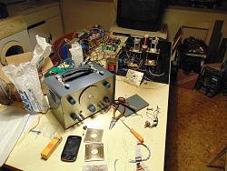
After an evening trying to destroy the old plasma and rebuild with new small frames. Now I got 2 oscillators in parallel, let's see if can be a good thing!
I accidentally swapped 6,3 with 12v filament and in a fraction of a second the last el84 (JJ, maybe are made of sugar) of 3 tube cascade I broke the filament of this new tube ....
Tiny flame for one second, really high blue from new gu50tube (maybe some air inside like first time of the other tube?)
I left everything on the table and came to sofa, it's useless to change coils now with tired mind, maybe Tomorrow I 'll find a good Equilibrium between coils!
For now, the only vantage is that this setup is so handy! Long wires for sure, but at least funny to change parts in few seconds!
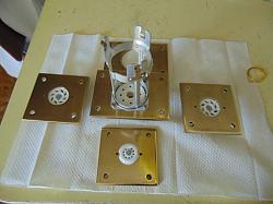
I post some picture of the new setup, the small frames are good, but I'm not satisfied of polishing...
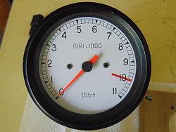
Only good news I have is that I found a nos rpm meter, old mechanical type Veglia Borletti, but don't know for what kind of motorbike can be!

PJs (Jul 16, 2016)
The tube bases look pretty good to me Stefano. To bad about he 6.3-12V mess up. Happens to the best of us...done that one my self and because I was all speed and no control...or double checks!Hopefully you can get a good deal on some replacements.
Not sure how you are hooking up 2 Oscillator circuits or if it will work...I'm assuming parallel some how to get the watts you are looking for? May have to futz with components if they aren't a matched set. How are you feeding both from the EL84? My ears are buzzing just thinking about it...
That tach probably came out of a Guzzi or Duck...but based on the red line probably a Duck. Nice find though!
Hope you got a good sleep and have better luck next round.
Thanks for the update, ~PJ
‘‘Always do right. This will gratify some people and astonish the rest.’’
Mark Twain
rendoman (Jul 16, 2016)
Thanks Pj!
It was not easy but somehow we made it to fire plasma!
Obviously I have to setup circuit "as new"
This circuit is Always possessed by the devil, brass socket are not grounded (now), if you put a wire from brass, and other tip in free air (aiming fire coil) flame x10 size with no movement of flame potentiometer, It's sign that something in circuit is not in correct place, above all synch of coils with air.
Strenght of field is great now, neon shows more light, and turns off in 60cm.
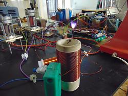
I have to study something about parallel oscillators, I see a great difference between emission of the 2 tubes in overdrive condition. Only one become bright red (see in first picture). I have to measure how much current each oscillator draws, at first sight I think we're close to half ampere at kv, seeing the color of anodes.
Currently I'm driving both with tiny el84, (with no sound because I broke one), DC voltage on G2 of oscillator is strong enough to keep these grids sshiny red, I'm not so sure that with new el34 amp the little el84 can keep the high AC signal from amplifier + DC ... I build 2 octal frames (plus preamp on relč socket for now) for this reason, 2x el34.
I noticed one thing, russian socket of gu50 have external pure aluminum frame, temperature of the thick brass frame is barely touchable even to the corners, I think something about 70 degree C. Not a problem for anode, that could be made from zirconium (I remember correctly?), and maybe that can help retain temperature to help oscillators.
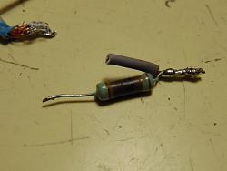
Bad note, as usual I'm a donkey and I like to pull circuit at maximum... I melt the tin weld of copper tip! that means that the lower part of tip reached about 200°C, That oblige me to make a mechanical connection with tungsten rod (as first setup)
Now it's time to try this new way!
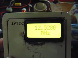
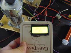
Don't know why frequency counter shows 12,5mhz as usual from coil, but 100mhz near oscilator tubes...maybe it takes some eddy frequencies.
With flat copper damaged tip flame is really large, not so high, but round, I want to see it with sharp point
PJs (Jul 18, 2016)
Because we love tubes, like women: hot !!!
Circuit is always strange, it runs only with a short wire connected to right metal socket and no contact on other side. Temperature of frame is high as hell running circuit hard, it's really difficult to touch brass.
At least now the 2 tubes runs togheter, with no more Chernobyl nuclear reactor 4 effect (maybe the air inside the new is finished?).
I'm not convinced that this path should be good, The only positive thing I see is that circuit is less sensitive to rf coil value. I see more power, but not so much to raise glasses.
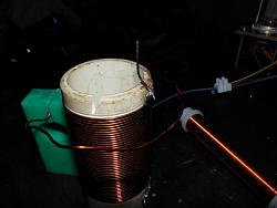
Strange thing, Ceramic cylinder is a bit conductive, in picture you can see a spark from ground wire. Maybe is dirty, or maybe it's like old bakelite socket that metallized with time?
I want to change some other parts, I make calculations for gu50 amp and el34, 18w vs 11w both in pentode, 6sn7 driver, maybe in srpp, now in single ended can pull 7volt undistorted, not enough to drive gu50.
... let's see in the next days!
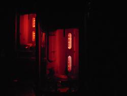

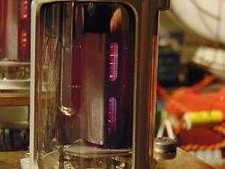
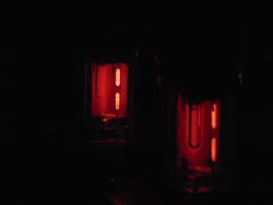
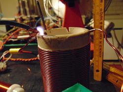
PJs (Jul 19, 2016)
There are currently 12 users browsing this thread. (0 members and 12 guests)
Bookmarks