Free 186 More Best Homemade Tools eBook:  
Get tool plans

User Tag List

Page 2 of 5 FirstFirst 1 2 3 4 5 LastLast
Results 11 to 20 of 44

Thread: Extending the range of calipers

  1. #11
    Supporting Member
    Join Date
    Jan 2016
    Location
    Southern tip of Vancouver Island
    Posts
    139
    Thanks
    957
    Thanked 40 Times in 28 Posts
    ¨The sagitta, ED (marked S in the diagram) is the distance from the chord to the circle's circumference¨

    Marv, in your diagram, the sagitta, marked S is the line segment EC, not ED (ED is half the chord BD, not the sagitta). Too lazy to check the rest of the math (too late, too much wine), so assume r and d expressions - and results correct within YMMV.

    186 More Best Homemade Tools eBook

  2. #12
    Supporting Member mklotz's Avatar
    Join Date
    Aug 2015
    Location
    LA, CA, USA
    Posts
    3,535
    Thanks
    362
    Thanked 6,563 Times in 2,161 Posts

    mklotz's Tools
    Quote Originally Posted by volodar View Post
    ¨The sagitta, ED (marked S in the diagram) is the distance from the chord to the circle's circumference¨

    Marv, in your diagram, the sagitta, marked S is the line segment EC, not ED (ED is half the chord BD, not the sagitta). Too lazy to check the rest of the math (too late, too much wine), so assume r and d expressions - and results correct within YMMV.
    Thanks for pointing it out. I must have been half asleep when I proofread that. It's fixed now.

    2,000+ Tool Plans
    ---
    Regards, Marv

    Failure is just success in progress
    That looks about right - Mediocrates

  3. The Following User Says Thank You to mklotz For This Useful Post:

    Paul Jones (Apr 20, 2019)

  4. #13
    Supporting Member Toolmaker51's Avatar
    Join Date
    Feb 2016
    Location
    Midwest USA
    Posts
    5,336
    Thanks
    7,044
    Thanked 3,012 Times in 1,901 Posts

    Toolmaker51's Tools
    I'm going to experiment with this, using parallel-jawed calipers. It shouldn't make a difference mathematically, but mechanically I wonder how relieved [pointed] outside jaws of a normal caliper interface in comparison.
    I've detected variance before relying on Starrett master verniers as final word over digitals, those instances when only a caliper was available. It's far easier detecting proper contact perpendicular to cylinders or flat parallel sides, vice a narrow 'bite' of angled models. Overall, spherical contact is most effective

    I'll perch caliper's spine on a pair of 1-2-3 blocks to establish that plane, easy part. The calculation could take me a week.
    I need to figure a large radius, seat of a missing bandsaw table pivot, a 36" machine. It will take Tony Foale's version to measure. It's about 5"Ø, and dang near 180°. Have plenty of tooling balls, but no two in same configuration.

    In lieu of that, will try a good-sized smaller cylinder and 3 gauge pins, starting with two of same size, third as a feeler. I expect greasing them, and a little manipulation so they 'find' centerline axis. Am I on the right track? Sounds like easy trig for a solution.
    What attracts me here, the weight of sample will assure appropriate contact, quite close to the real thing, minus actual table. It is too big for casual handling, at about 34" square and 2.5" thick. Once the new cylinder is made, milling a flat, bolt holes and dowels will finish it off.
    Sincerely,
    Toolmaker51
    ...we'll learn more by wandering than searching...

  5. The Following User Says Thank You to Toolmaker51 For This Useful Post:

    Paul Jones (Apr 20, 2019)

  6. #14
    Supporting Member tonyfoale's Avatar
    Join Date
    Nov 2016
    Location
    Spain
    Posts
    1,612
    Thanks
    726
    Thanked 2,721 Times in 728 Posts

    tonyfoale's Tools
    Quote Originally Posted by Toolmaker51 View Post
    I'll perch caliper's spine on a pair of 1-2-3 blocks to establish that plane, easy part. The calculation could take me a week.
    I need to figure a large radius, seat of a missing bandsaw table pivot, a 36" machine. It will take Tony Foale's version to measure. It's about 5"Ø, and dang near 180°.
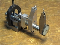
    What I made is pretty simple and very quick to make. You don't even have to do any calcs. I uploaded a bit of software to do the heavy lifting.

  7. The Following 2 Users Say Thank You to tonyfoale For This Useful Post:

    olderdan (Apr 13, 2019), Toolmaker51 (Apr 13, 2019)

  8. #15
    Supporting Member Toolmaker51's Avatar
    Join Date
    Feb 2016
    Location
    Midwest USA
    Posts
    5,336
    Thanks
    7,044
    Thanked 3,012 Times in 1,901 Posts

    Toolmaker51's Tools
    Quote Originally Posted by tonyfoale View Post
    What I made is pretty simple and very quick to make. You don't even have to do any calcs. I uploaded a bit of software to do the heavy lifting.
    Absolutely intend duplicating your device. I'll cut a paper template to estimate spread of contacts and length needed for indicator stem, though using a depth mic in a reamed hole might help. When I depth radii, a ball or rod makes an ideal seat.
    As goal's equivalent of a slip fit, with the saw and running lathe separated by 70 miles, certainty is an issue. There's ways to address a few thou' under by shimming. I'd trust blue spring stock to not gall under load. Over-size not so easily, unless I hold off separating work piece from spud being chucked. The shoe, being so 180° will reject less than correct fit.

    Now, as to your software capable of heavy lifting; has it a winch attached?
    Lol.

    PS to interested readers. All my projects work under same restrictions, need here - power there. And 'need here' are the projects getting my electricity in doors; 3ph 440v. I had caplock mistakenly down for that, which also related in #PH$$).
    Lol again.
    Sincerely,
    Toolmaker51
    ...we'll learn more by wandering than searching...

  9. #16
    Supporting Member tonyfoale's Avatar
    Join Date
    Nov 2016
    Location
    Spain
    Posts
    1,612
    Thanks
    726
    Thanked 2,721 Times in 728 Posts

    tonyfoale's Tools
    Quote Originally Posted by Toolmaker51 View Post
    Now, as to your software capable of heavy lifting; has it a winch attached?
    Lol.
    I think that I put a link to it in my original post or else it is in the PDF that is mentioned in the original post. If you cannot find it, tell me and I'll check where it is.
    I am off to bed now, it's late as I have just finished watching the delayed qualifying at COTA in TX. The old fella did well.

  10. #17
    Supporting Member Paul Alciatore's Avatar
    Join Date
    Mar 2014
    Location
    Beaumont, TX
    Posts
    304
    Thanks
    9
    Thanked 157 Times in 83 Posts

    Paul Alciatore's Tools
    Marv, That is a great method. I just have to play with it.

    One additional source of error that I see is the fact that most caliper jaws are very narrow as well as having a sharp point. So there is very little area that bears on the part being measured and they can easily make a dent of unknown depth in it. A gentle technique is definitely in order.
    Paul A.

  11. #18
    Supporting Member tonyfoale's Avatar
    Join Date
    Nov 2016
    Location
    Spain
    Posts
    1,612
    Thanks
    726
    Thanked 2,721 Times in 728 Posts

    tonyfoale's Tools
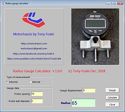
    Here is a link to my calculation software, it is an unrestricted download.
    RadiusGauge software

    It will work equally well with Marv's method.

    Extending the range of calipers-software.jpg Click image for full size version.

    To use with Marv's method.
    1. Chose "External" for type of measurement.
    2. "Ball diameter' set to zero.
    3. "Probe spacing" is the caliper reading.
    4. "Gauge displacement" is the height (length) of the caliper jaws.

    As a test I used Marv's figures, which were:
    <<
    For the bench block pictured, I made the following measurements...
    c = 2.859 (no. 3 in my list)
    s = 1.159 (no. 4 in my list)

    and computed a diameter of 2.922.
    >>

    The software came up with a radius of 1.461 which is the same as Marv's result.

  12. The Following 3 Users Say Thank You to tonyfoale For This Useful Post:

    Jon (Apr 18, 2019), Paul Jones (Apr 20, 2019), that_other_guy (Apr 24, 2019)

  13. #19
    Jon
    Jon is offline Jon has agreed the Seller's Terms of Service
    Administrator
    Supporting Member
    Jon's Avatar
    Join Date
    Jan 2012
    Location
    Colorado, USA
    Posts
    26,473
    Thanks
    8,122
    Thanked 40,327 Times in 11,792 Posts
    Congratulations mklotz - your Circular Object Radius Computation Method is the Homemade Tool of the Week!

    This win is particularly notable because, as mklotz mentions, it advances the same principle seen in a previous award-winning tool by tonyfoale. It will be interesting to see if someone can iterate upon it further.

    Some nice entries this week:

    Bandsaw Floating Jaws by rgsparber
    Lever Feed Mini Lathe Tailstock by threesixesinarow
    Brake System Bleeder by The Aussie Shed
    Sheetmetal Punch by janochek
    Bandsaw Vise Screw Jack by rgsparber
    Jigsaw Cutting Station by Junkyard
    Threaded Rod Cutting Fixture by rgsparber
    Scratch Stock Beading Tool by Mikhandmaker
    Lathe Centering Tool by Vyacheslav.Nevolya
    Axle Stand by PowerMk
    Lathe Split Nut by bobneumann
    Trailer Axle Ends by Menga
    Solid State Engine Design by TilenThaler
    Battery Spot Welder by mariost
    Kant Twist Clamp by Kwandotechnic
    Center Drilling Fixture by kess
    Cultivator by GabrielR
    Drill Press Lift System by tonyfoale
    Slag Chipping Hammer by Raytonian


    mklotz - we've added your tool entry to our All Homemade Tool of the Week winners post. And, you'll be receiving a $25 online gift card, in your choice of Amazon, PayPal, or bitcoin. Please PM me your current email address and gift card choice and I'll get it sent over right away.

    This is your 13th Homemade Tool of the Week win. Nice work

    Here are all of your winning homemade tools:

    New plans added on 12/02/2024: Click here for 2,609 plans for homemade tools.

  14. #20
    Supporting Member old_toolmaker's Avatar
    Join Date
    Dec 2017
    Location
    Cape Coral, FL
    Posts
    579
    Thanks
    647
    Thanked 457 Times in 184 Posts

    old_toolmaker's Tools

    Solving for Chord.

    This method works well, but the accuracy is dependent upon the condition of the caliper jaw tips. If they are worn from use, accuracy, will be compromised accordingly.
    Back in my early years before the electronic calculator, we solved these trigonometric issues via long hand with pencil and paper.
    Dick


    Links to some of my plans:

    https://www.homemadetools.net/forum/...965#post105972 OFF-SET TAILSTOCK CENTER PLANS
    http://www.homemadetools.net/forum/s...995#post112113 SMALL TURRET TOOL POST PLANS
    http://www.homemadetools.net/forum/l...994#post112111 LARGE TURRET TOOL POST PLANS
    http://www.homemadetools.net/forum/m...383#post110340 MINI-LATHE CARRIAGE LOCK PLANS
    http://www.homemadetools.net/forum/s...191#post106483 SMALL QC TOOL POST PLANS
    http://www.homemadetools.net/forum/q...849#post119345 QUICK CHANGE LATHE TURRET
    http://www.homemadetools.net/forum/m...949#post119893 MINI LATHE COMPOUND PIVOT MODIFICATION

Thread Information

Users Browsing this Thread

There are currently 1 users browsing this thread. (0 members and 1 guests)

Bookmarks

Posting Permissions

  • You may not post new threads
  • You may not post replies
  • You may not post attachments
  • You may not edit your posts
  •