Free 186 More Best Homemade Tools eBook:  
Get 2,500+ tool plans, full site access, and more.

User Tag List

Page 2 of 3 FirstFirst 1 2 3 LastLast
Results 11 to 20 of 27

Thread: Dust extraction - sizing

  1. #11
    Supporting Member
    Join Date
    Sep 2018
    Posts
    2,401
    Thanks
    11,416
    Thanked 1,245 Times in 680 Posts

    nova_robotics's Tools
    But I might be wrong. My gut feel says strongly that you want high air velocity. But gut feel can lead us astray, so I just worked it out from a head loss perspective. Going from 4" round duct to 6" round duct will save you about half a PSI. The 4" will have about 0.7 PSI of loss, and the 6" will have about 0.1 PSI. For a shop vacuum that may only make -3 PSI (guessing here), that may be significant. You might very well get 10-20% more suction at your endpoint by increasing the duct diameter.

    It's a tradeoff. All I know is I don't want to mess around with removing sections of duct to try to unclog them, so I'm installing 4" in my shop.

    186 More Best Homemade Tools eBook

  2. #12
    Supporting Member tonyfoale's Avatar
    Join Date
    Nov 2016
    Location
    Spain
    Posts
    1,625
    Thanks
    733
    Thanked 2,737 Times in 733 Posts

    tonyfoale's Tools
    Quote Originally Posted by nova_robotics View Post
    For a shop vacuum that may only make -3 PSI (guessing here), ................................

    It's a tradeoff. All I know is I don't want to mess around with removing sections of duct to try to unclog them, so I'm installing 4" in my shop.
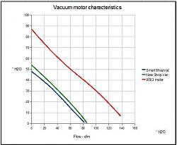
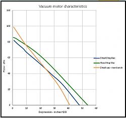
    I have measured various shopvacs and none get to 3 psi with useful flow. Here are the results of tests of different shopvacs, without further explanation. The axes show pressure in inches WG, for reference 28" is 1psi.

    Dust extraction - sizing-vacmotorcomparison02.jpg Dust extraction - sizing-vacmotors_01.jpg

    2,500+ Tool Plans

  3. The Following 3 Users Say Thank You to tonyfoale For This Useful Post:

    EnginePaul (Jan 12, 2022), mwmkravchenko (Jan 12, 2022), nova_robotics (Jan 11, 2022)

  4. #13
    Supporting Member
    Join Date
    Sep 2018
    Posts
    2,401
    Thanks
    11,416
    Thanked 1,245 Times in 680 Posts

    nova_robotics's Tools
    Quote Originally Posted by tonyfoale View Post
    I have measured various shopvacs and none get to 3 psi with useful flow. Here are the results of tests of different shopvacs, without further explanation. The axes show pressure in inches WG, for reference 28" is 1psi.

    Click image for larger version. 

Name:	VacMotorComparison02.jpg 
Views:	190 
Size:	34.4 KB 
ID:	41505 Click image for larger version. 

Name:	VacMotors_01.jpg 
Views:	178 
Size:	49.9 KB 
ID:	41506
    I am amazed you have this information.

  5. The Following User Says Thank You to nova_robotics For This Useful Post:

    mwmkravchenko (Jan 12, 2022)

  6. #14
    Supporting Member tonyfoale's Avatar
    Join Date
    Nov 2016
    Location
    Spain
    Posts
    1,625
    Thanks
    733
    Thanked 2,737 Times in 733 Posts

    tonyfoale's Tools
    Quote Originally Posted by nova_robotics View Post
    I am amazed you have this information.
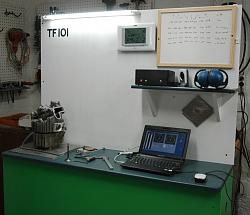
    I needed the info when designing my flow bench.

    Dust extraction - sizing-flowbench_03.jpg

  7. #15
    Supporting Member hemmjo's Avatar
    Join Date
    Feb 2017
    Posts
    2,706
    Thanks
    255
    Thanked 1,527 Times in 862 Posts

    hemmjo's Tools
    There are a few other things to keep in mind when assembling your system.

    If your main duct is on the floor, just skip to #3.

    1) If your main duct runs over head, the tap from each machine needs to enter the main duct on the side. It they enter from the bottom, eddy currents created by air and shavings passing over the unused openings, will soon fill the ducts entering from the bottom.

    2) If your power unit is below the overhead duct, the duct and elbow rising up to meet main can be the larger size to help minimize pressure loss. The shavings will fall into the collector anyway.

    3) If your duct is plastic, you are also building a static electric generator. There are a a few ways to eliminate that. Like this, OR this, or any similar method.

  8. #16
    Supporting Member
    Join Date
    Sep 2018
    Posts
    2,401
    Thanks
    11,416
    Thanked 1,245 Times in 680 Posts

    nova_robotics's Tools
    Quote Originally Posted by tonyfoale View Post
    I needed the info when designing my flow bench.

    Click image for larger version. 

Name:	FlowBench_03.JPG 
Views:	122 
Size:	94.1 KB 
ID:	41507
    That's interesting. I've never had the opportunity to mess with one, but I've wondered about mounting a loudspeaker to do Helmholtz resonance tuning as well as flow. Is that a thing that people do?

  9. #17
    Supporting Member
    Join Date
    Dec 2016
    Posts
    332
    Thanks
    3
    Thanked 126 Times in 101 Posts
    If you are collecting or conveying any combustible material and you don't want to get shocked, you may want to run a solid copper ground wire inside the entire duct run. Ground the end to a good earth or system ground to eliminate static build up. I can attest to this because I have been knocked on my ass a few times!

  10. The Following User Says Thank You to owen moore For This Useful Post:

    mwmkravchenko (Jan 12, 2022)

  11. #18
    Supporting Member mwmkravchenko's Avatar
    Join Date
    Nov 2017
    Location
    Perth Ontario Canada
    Posts
    1,044
    Thanks
    5,311
    Thanked 397 Times in 282 Posts
    Quote Originally Posted by nova_robotics View Post
    That's interesting. I've never had the opportunity to mess with one, but I've wondered about mounting a loudspeaker to do Helmholtz resonance tuning as well as flow. Is that a thing that people do?
    You are trying to modulate the flow and see where the intake or exhaust manifold is at resonance ?

    With a sufficiently large diaphragm woofer you can move a fair bit of air. The problem is that is is not unidirectional. It is push pull. Tony I think is looking for unidirectional flow.

    I do a fair bit of vacuum bag veneering and clamping. I can tell you that a decent small shop vac can get you quite a serious vacuum for those purposes. that 3 PSI is over every square inch of surface. pretty useful for clamping. I have helped one machine shop come up with a vacuum plate arrangement that allowed them to machine things with no visible clamping method. A deeply drawn vacuum can give you near 15 PSI.

    When I started doing this in the early 90's I broke many pieces of wood and molds learning their structural limits. Also discovered a neat thing call a variable vacuum switch. The reverse of a compressor switch.

  12. #19
    Supporting Member tonyfoale's Avatar
    Join Date
    Nov 2016
    Location
    Spain
    Posts
    1,625
    Thanks
    733
    Thanked 2,737 Times in 733 Posts

    tonyfoale's Tools
    Quote Originally Posted by mwmkravchenko View Post
    You are trying to modulate the flow and see where the intake or exhaust manifold is at resonance ?
    Pressure waves can be very important to the performance of highly tuned engines. I pointed out that the suggestion to evaluate this on a flow bench would have problems due to the need to emulate very high exhaust temperatures, because the wave velocity various with temperature.

    Quote Originally Posted by mwmkravchenko View Post
    .... Tony I think is looking for unidirectional flow.
    Actually I test flow in both directions. The wave action at certain parts of the cycle at different RPM causes reverse flow. It is good if you can reduce the reverse flow without reducing the forward flow. Hence the two way testing.

  13. #20
    Supporting Member mwmkravchenko's Avatar
    Join Date
    Nov 2017
    Location
    Perth Ontario Canada
    Posts
    1,044
    Thanks
    5,311
    Thanked 397 Times in 282 Posts
    Quote Originally Posted by tonyfoale View Post
    Pressure waves can be very important to the performance of highly tuned engines. I pointed out that the suggestion to evaluate this on a flow bench would have problems due to the need to emulate very high exhaust temperatures, because the wave velocity various with temperature.


    Actually I test flow in both directions. The wave action at certain parts of the cycle at different RPM causes reverse flow. It is good if you can reduce the reverse flow without reducing the forward flow. Hence the two way testing.
    OK Makes sense.

    Speed of sound varies with the temperature of the medium it is measured in. As does the amplitude of the sounds power. Easier to have a nigher amplitude for a given power input in a warmer medium, air mixture in this case.

    Warmer air easier to transmit sound through vibrations in such a system. It is still the compression and rarefaction of air.

Thread Information

Users Browsing this Thread

There are currently 1 users browsing this thread. (0 members and 1 guests)

Tags for this Thread

Bookmarks

Posting Permissions

  • You may not post new threads
  • You may not post replies
  • You may not post attachments
  • You may not edit your posts
  •