Free 186 More Best Homemade Tools eBook:  
Get 2,500+ tool plans, full site access, and more.

User Tag List

Page 1 of 2 1 2 LastLast
Results 1 to 10 of 11

Thread: Drill sharpening jig and grinder

  1. #1
    Supporting Member th62's Avatar
    Join Date
    Oct 2015
    Posts
    287
    Thanks
    0
    Thanked 512 Times in 172 Posts

    th62's Tools

    Drill sharpening jig and grinder

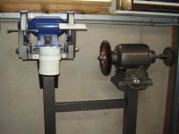
    This is a drill sharpening jig I made some time ago and the grinder setup I use it on. The grinder is just an el cheapo, I've been meaning to change the grinder as the wheels wobble all over the place. One day I may even get around to replacing it.

    Anyway some details on both.

    The Jig:

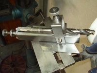
    I used a piece of 25mm square bar, linished it, milled a V for the drill, cut a 2mm slot down the centre for 110mm, drilled a stepped hole through: 5mm for 30mm and then 11.5 mm for the remaining 110mm. I had to extend an old 11.5mm drill and grind flat on the end so I could machine the end of the hole flat for a stepped bush to run on. I also drilled a couple of debris drain holes and tapped a few 5mm holes for mounting the slide plate, the end plate and the drill clamp. As you can see from the pics there are quite a few bits inside.

    The 5mm advance rod was turned down to 3.5 on the end and a 5mm bush with collar was shrunk in place for the end bushing. I turned a bit of stock to 7mm, threaded the inside to 5mm x .8, fashioned a single wing and tacked it to the nut. The bush on the advance end was machined to 7mm with a collar, machined down to fit a 9mm spanner, and threaded inside the same as the advance screw. When screwed into place it’s locked off with a locknut. The plate on the end has a backlash adjuster and locknut and also acts as the outer bearing for the advance screw bush. The end plate is fixed by two 5mm allen heads which I had to turn down to accommodate the backlash adjuster locknut. To the rear of that are the thumb lock nut and the thumb adjuster.

    The drill clamp U piece is attached via two 5mm allen heads. I machined a stepped 5mm nut and shrunk it into the top of the U piece. The adjuster screw has a thumb nut attached at the top and the adjuster screw pushes an H shaped plate down onto the drill flutes.

    It will accommodate drills from 13mm down to 2mm, larger bits are probably better ground using a simple conical grinding jig attached to a linisher. Anything under 4 or 5mm would be difficult to grind accurately on this jig, so another project would be for a jig with a drill chuck for smaller bits.

    In use: The drill is secured in place by the adjuster and H plate. To advance the drill onto the grindstone, the advance thumbnut is turned and the single winged nut moves along the advance screw, guided by the slot in the bed, and acts on the rear of drill pushing it forward and onto the grindstone...

    Over complicated? Sure is, but it works well; and, it was an excellent project to design and make.

    The grinder and tables:

    The framework you see in the picture is made from 25 x 1.6mm RHS. each side has two rails along which slide the table supports, they can be adjusted for angle as well as reach. There are also a couple of L shaped plates to which the table stem mounting bolts are welded. These brackets stop the bolts turning when tightening the stem securing nuts.

    The table has scribed lines at 0, 30, 45, 60 and 90 degrees, the other two tables have slots, one for the drill jig the other for a lathe bit sharpener.
    I joined this grinder stand to my 8" grinder stand with a short section of 50 x 25mm RHS. The 8" runs a wire wheel and buffing pads (horrid job). The 6" grinder is set at around chest height so I don't have to stoop whereas the 8" is set much lower. I also stripped, cleaned and tidied up the wiring underneath and then painted it in hammertone along with the stand. There is also a water trough at front so I don't have to go searching for a water bucket at inopportune times.

    I've been using the jig and grinder for quite a while now, I do wish I had made the table stems and rails from gal RHS though as the paint tends to peel off from the constant changing of table position.
    Attached Thumbnails Attached Thumbnails Drill sharpening jig and grinder-1.jpg   Drill sharpening jig and grinder-2.jpg   Drill sharpening jig and grinder-3.jpg   Drill sharpening jig and grinder-4.jpg   Drill sharpening jig and grinder-5.jpg  

    Drill sharpening jig and grinder-6.jpg   Drill sharpening jig and grinder-7.jpg   Drill sharpening jig and grinder-8.jpg   Drill sharpening jig and grinder-10.jpg  
    Attached Images Attached Images  

    186 More Best Homemade Tools eBook

  2. The Following 23 Users Say Thank You to th62 For This Useful Post:

    Andyt (Dec 19, 2019), big o (Dec 14, 2017), bobstar (Oct 27, 2020), Christophe Mineau (Nov 7, 2017), drivermark (Nov 6, 2017), H.L (Oct 15, 2015), HobieDave (May 24, 2024), Home-PC (Dec 19, 2019), Jon (Oct 8, 2015), kbalch (Oct 9, 2015), LMMasterMariner (Nov 8, 2017), Metallurg33 (Apr 9, 2018), NortonDommi (Nov 6, 2017), Okapi (Apr 17, 2016), old_toolmaker (Dec 18, 2019), Paul Jones (Oct 9, 2015), Philip Davies (May 22, 2024), PJs (Oct 9, 2015), rlm98253 (Nov 6, 2017), Tenn (Dec 18, 2019), thoms_here (Nov 11, 2017), threesixesinarow (Mar 16, 2019), Toolmaker51 (Apr 8, 2018)

  3. #2
    Content Editor
    Supporting Member
    DIYer's Avatar
    Join Date
    Aug 2013
    Posts
    3,055
    Thanks
    798
    Thanked 1,897 Times in 1,692 Posts
    That's some jig! Yes, I will admit that I find it a tad complicated, but there's no denying the quality of the jig itself and the end result.

    2,500+ Tool Plans

  4. #3
    Content Editor
    Supporting Member
    DIYer's Avatar
    Join Date
    Aug 2013
    Posts
    3,055
    Thanks
    798
    Thanked 1,897 Times in 1,692 Posts
    Thanks th62! We've added your Drill Sharpening Jig to our Drilling and Drill Presses category, as well as to your builder page: th62's Homemade Tools. Your receipt:


  5. #4
    Content Editor
    Supporting Member
    DIYer's Avatar
    Join Date
    Aug 2013
    Posts
    3,055
    Thanks
    798
    Thanked 1,897 Times in 1,692 Posts
    Thanks th62! We've added your Grinder Stand to our Dollies and Stands category, as well as to your builder page: th62's Homemade Tools. Your receipt:


  6. The Following User Says Thank You to DIYer For This Useful Post:

    thoms_here (Nov 11, 2017)

  7. #5
    Supporting Member Paul Jones's Avatar
    Join Date
    May 2014
    Location
    Del Mar, California
    Posts
    1,231
    Thanks
    5,810
    Thanked 1,463 Times in 657 Posts

    Paul Jones's Tools
    The drill ground finishes are excellent and the jig is so well made. This is one of those tools that will be very popular. Thank you for sharing the detailed photos of the jig and grinder tables.

  8. #6

    Join Date
    Oct 2015
    Posts
    4
    Thanks
    0
    Thanked 0 Times in 0 Posts

    Query

    Without drawings I am having a hard time understanding how you index the drill bit being sharpened from one face to the other.And how do you get the double cut on each face?

    Quote Originally Posted by th62 View Post
    This is a drill sharpening jig I made some time ago and the grinder setup I use it on. The grinder is just an el cheapo, I've been meaning to change the grinder as the wheels wobble all over the place. One day I may even get around to replacing it.

    Anyway some details on both.

    The Jig:

    I used a piece of 25mm square bar, linished it, milled a V for the drill, cut a 2mm slot down the centre for 110mm, drilled a stepped hole through: 5mm for 30mm and then 11.5 mm for the remaining 110mm. I had to extend an old 11.5mm drill and grind flat on the end so I could machine the end of the hole flat for a stepped bush to run on. I also drilled a couple of debris drain holes and tapped a few 5mm holes for mounting the slide plate, the end plate and the drill clamp. As you can see from the pics there are quite a few bits inside.

    The 5mm advance rod was turned down to 3.5 on the end and a 5mm bush with collar was shrunk in place for the end bushing. I turned a bit of stock to 7mm, threaded the inside to 5mm x .8, fashioned a single wing and tacked it to the nut. The bush on the advance end was machined to 7mm with a collar, machined down to fit a 9mm spanner, and threaded inside the same as the advance screw. When screwed into place it’s locked off with a locknut. The plate on the end has a backlash adjuster and locknut and also acts as the outer bearing for the advance screw bush. The end plate is fixed by two 5mm allen heads which I had to turn down to accommodate the backlash adjuster locknut. To the rear of that are the thumb lock nut and the thumb adjuster.

    The drill clamp U piece is attached via two 5mm allen heads. I machined a stepped 5mm nut and shrunk it into the top of the U piece. The adjuster screw has a thumb nut attached at the top and the adjuster screw pushes an H shaped plate down onto the drill flutes.

    It will accommodate drills from 13mm down to 2mm, larger bits are probably better ground using a simple conical grinding jig attached to a linisher. Anything under 4 or 5mm would be difficult to grind accurately on this jig, so another project would be for a jig with a drill chuck for smaller bits.

    In use: The drill is secured in place by the adjuster and H plate. To advance the drill onto the grindstone, the advance thumbnut is turned and the single winged nut moves along the advance screw, guided by the slot in the bed, and acts on the rear of drill pushing it forward and onto the grindstone...

    Over complicated? Sure is, but it works well; and, it was an excellent project to design and make.

    The grinder and tables:

    The framework you see in the picture is made from 25 x 1.6mm RHS. each side has two rails along which slide the table supports, they can be adjusted for angle as well as reach. There are also a couple of L shaped plates to which the table stem mounting bolts are welded. These brackets stop the bolts turning when tightening the stem securing nuts.

    The table has scribed lines at 0, 30, 45, 60 and 90 degrees, the other two tables have slots, one for the drill jig the other for a lathe bit sharpener.
    I joined this grinder stand to my 8" grinder stand with a short section of 50 x 25mm RHS. The 8" runs a wire wheel and buffing pads (horrid job). The 6" grinder is set at around chest height so I don't have to stoop whereas the 8" is set much lower. I also stripped, cleaned and tidied up the wiring underneath and then painted it in hammertone along with the stand. There is also a water trough at front so I don't have to go searching for a water bucket at inopportune times.

    I've been using the jig and grinder for quite a while now, I do wish I had made the table stems and rails from gal RHS though as the paint tends to peel off from the constant changing of table position.

  9. #7
    Supporting Member th62's Avatar
    Join Date
    Oct 2015
    Posts
    287
    Thanks
    0
    Thanked 512 Times in 172 Posts

    th62's Tools
    Indexing is the same as with the tormek, line the chisel edge up withe jig! I do have an indexer for it but never use it, pretty much useless with smaller bits. Chisel and relief angles are adjusted via the table.

  10. The Following User Says Thank You to th62 For This Useful Post:

    Jon (Oct 12, 2015)

  11. #8
    WNL
    WNL is offline
    Banned
    Join Date
    Feb 2017
    Posts
    3
    Thanks
    5
    Thanked 2 Times in 1 Post

    Grinder wheel

    Quote Originally Posted by th62 View Post
    This is a drill sharpening jig I made some time ago and the grinder setup I use it on. The grinder is just an el cheapo, I've been meaning to change the grinder as the wheels wobble all over the place. One day I may even get around to replacing it.

    Anyway some details on both.

    The Jig:

    I used a piece of 25mm square bar, linished it, milled a V for the drill, cut a 2mm slot down the centre for 110mm, drilled a stepped hole through: 5mm for 30mm and then 11.5 mm for the remaining 110mm. I had to extend an old 11.5mm drill and grind flat on the end so I could machine the end of the hole flat for a stepped bush to run on. I also drilled a couple of debris drain holes and tapped a few 5mm holes for mounting the slide plate, the end plate and the drill clamp. As you can see from the pics there are quite a few bits inside.

    The 5mm advance rod was turned down to 3.5 on the end and a 5mm bush with collar was shrunk in place for the end bushing. I turned a bit of stock to 7mm, threaded the inside to 5mm x .8, fashioned a single wing and tacked it to the nut. The bush on the advance end was machined to 7mm with a collar, machined down to fit a 9mm spanner, and threaded inside the same as the advance screw. When screwed into place it’s locked off with a locknut. The plate on the end has a backlash adjuster and locknut and also acts as the outer bearing for the advance screw bush. The end plate is fixed by two 5mm allen heads which I had to turn down to accommodate the backlash adjuster locknut. To the rear of that are the thumb lock nut and the thumb adjuster.

    The drill clamp U piece is attached via two 5mm allen heads. I machined a stepped 5mm nut and shrunk it into the top of the U piece. The adjuster screw has a thumb nut attached at the top and the adjuster screw pushes an H shaped plate down onto the drill flutes.

    It will accommodate drills from 13mm down to 2mm, larger bits are probably better ground using a simple conical grinding jig attached to a linisher. Anything under 4 or 5mm would be difficult to grind accurately on this jig, so another project would be for a jig with a drill chuck for smaller bits.

    In use: The drill is secured in place by the adjuster and H plate. To advance the drill onto the grindstone, the advance thumbnut is turned and the single winged nut moves along the advance screw, guided by the slot in the bed, and acts on the rear of drill pushing it forward and onto the grindstone...

    Over complicated? Sure is, but it works well; and, it was an excellent project to design and make.

    The grinder and tables:

    The framework you see in the picture is made from 25 x 1.6mm RHS. each side has two rails along which slide the table supports, they can be adjusted for angle as well as reach. There are also a couple of L shaped plates to which the table stem mounting bolts are welded. These brackets stop the bolts turning when tightening the stem securing nuts.

    The table has scribed lines at 0, 30, 45, 60 and 90 degrees, the other two tables have slots, one for the drill jig the other for a lathe bit sharpener.
    I joined this grinder stand to my 8" grinder stand with a short section of 50 x 25mm RHS. The 8" runs a wire wheel and buffing pads (horrid job). The 6" grinder is set at around chest height so I don't have to stoop whereas the 8" is set much lower. I also stripped, cleaned and tidied up the wiring underneath and then painted it in hammertone along with the stand. There is also a water trough at front so I don't have to go searching for a water bucket at inopportune times.

    I've been using the jig and grinder for quite a while now, I do wish I had made the table stems and rails from gal RHS though as the paint tends to peel off from the constant changing of table position.
    Hi TH62 , you can true your grinder wheel with the flat diamond sides of any diamond concrete cutting disc. I bought a diamond dressing tool and after using it on my smaller grinders, thought that a D C disk might work.
    So I took a used disk and tried it on my 200mm grinder and was surpised at the outcome.
    You don't need to go and buy the dressing tool...
    Cheers Willie

  12. #9

    Join Date
    Apr 2017
    Posts
    9
    Thanks
    0
    Thanked 1 Time in 1 Post
    I teach Precision Machining at a career center and am also involved with SkillsUSA Indiana.

    I am interested in starting a new competition for SkillsUSA's precision machining, and CNC categories where students MAKE a product from one piece of metal.
    I would love to have a copy of your plans for the drill bit sharpener. I think it could be an excellent product idea for these competitions.

    Thanks
    Joe

  13. #10
    Supporting Member Toolmaker51's Avatar
    Join Date
    Feb 2016
    Location
    Midwest USA
    Posts
    5,338
    Thanks
    7,048
    Thanked 3,021 Times in 1,905 Posts

    Toolmaker51's Tools
    Reviewing long after OP, this remains an excellent project.
    I know full-fledged shops running large lathes, radial drills, horizontal boring mills, etc with zero drill grinding beyond disc and belt sanders. Matters not how long they've been in business, range of machinery, or staff size/ experience.
    Unless machine tools are supported by service machines or inventive Toolmakers, they ain't really 'fledged' at all. Some (especially accountants) will argue tying up capital in lesser used equipment is bad practice. "We can send that work out!"
    Ask them where to buy a sharp 2 1/2" bit mid-shift, around 10 pm. Or time invested hand sharpening same bit. . .to continue work on that $2000 billet.

    The only facet making th62's fixture seem complicated, is he replicates by fabricating what is not sold so readily, and had been primarily of castings. They same type of carrier also is used on inclined [59°] swiveling grind fixtures.
    Sincerely,
    Toolmaker51
    ...we'll learn more by wandering than searching...

Thread Information

Users Browsing this Thread

There are currently 1 users browsing this thread. (0 members and 1 guests)

Bookmarks

Posting Permissions

  • You may not post new threads
  • You may not post replies
  • You may not post attachments
  • You may not edit your posts
  •