A while back there was a thread on fly cutters, but I can't find it now. I didn't start the thread but I mentioned my use of multiple cutters and preference for inertia. I have just needed to use one of my fly cutters and had a camera handy, so here is a full description with pix.
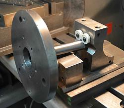
Firstly I needed a substantial mounting method for the heavy rotor containing the cutting tools. An R8 to 100 mm chuck mounting flange was ideal, these are cheap and it saved me a lot of work.
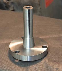
The R8 to chuck mounting flange.
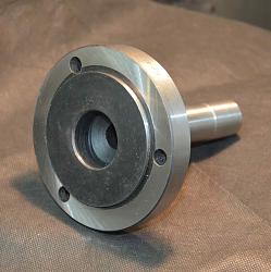
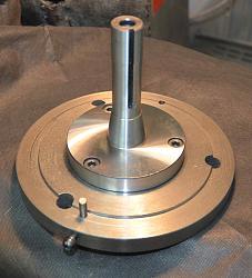
This has a 72 mm diameter spigot for location and three holes for M8 mounting bolts. The rotor was made from an old chuck plate which gives plenty of the inertia which I regard as important for fly cutters. It was faced off, drilled and tapped for mounting and a register bored to suit the spigot on the mounting plate. Two opposing holes were drilled to take 0.25" tool blanks, holes were drilled and tapped M6 at 90 deg. to take grub screws to hold the tools. This allows me easy depth of cut adjustment, and the circular tools allow rotational adjustment to change the rake angle for different work piece material. I have a choice of grinding tools from HSS blanks or more usually I grind the tools from old 0.25" carbide milling cutters.
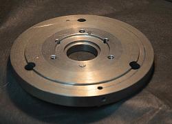
On the left is the base rotor, 190 mm diameter. There are a few surplus holes, a legacy of its prior use. To the right is the complete assembly.
The assembly mounted on my static crankshaft balancer. I think that I have described that in a prior posting.
Now we come to the reason for the two cutting tools. One is set at a slightly greater radius, about 6 mm, than the other. The tool at the larger radius will hit the work first on each revolution followed by the second tool. I set the first tool at a height suitable for a roughing cut and the second tool gets set an amount lower to act as a finishing cut. In effect this gives me two passes in one. Each tool can be ground differently to suit the different needs of roughing and finishing.
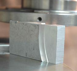
Here we can see the two surfaces made by each tool in turn. In this case the second cutter was set about 0.5 mm deeper than the first for demonstration purposes. In reality one would take a shallower finishing cut.
Alternatively, both tools could be set such that each removes a similar depth of material, this allows the fly cutter to take double the material in a single pass as compared to a single tool cutter.
This video shows the setting procedure and a demonstration work piece cut.


 LinkBack URL
 About LinkBacks


 Reply With Quote




Bookmarks