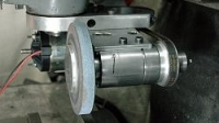
A while back I made a toolpost grinder for my lathe from a treadmill DC motor and the spindle from a small mill/drill that I found at a flea market.
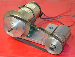
Click thumbnails for full size.
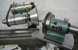
I also used it on my T&C grinder which was featured here
http://www.homemadetools.net/forum/h...6205#post83247
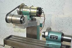
T&C grinder with same head.
For some time I have needed a surface grinder and have been thinking about attaching the same grinding head to my mill. My Bridgeport was fitted from new with an early Anilam CNC system which I have ungraded to PC control. The CNC would allow for automatic X and Y traverse and Z depth of cut adjustment. I had put this job off because I thought that I had more pressing jobs and I thought that it would take more time than I wanted to spend on it.
Attaching a grinder to a mill for this purpose is not a new idea in this forum, but others I have seen have fixed the grinder to the frame structure of the mill. I wanted to attach it to the quill for depth control.
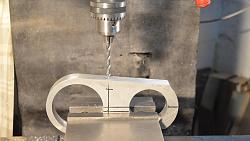
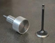
I realised that I would need to make a clamp around the quill but I had already made a couple to hold a high speed air spindle and later an electric spindle. Looking at those I saw that if I turned the grinding head upside down I could bolt it to the electric spindle clamp. Drill 4 mounting holes in the clamp and drill and tap 4 holes in the grinding head base plate. That didn't seem like it would take too long, a reasonable price to remove an item from my todo list.
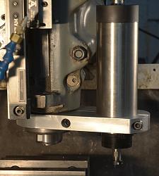
High speed spindle clamp.
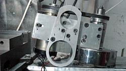
Showing the four bolts holding the grinding head to the quill clamp. 1. is countersunk to avoid fouling the quill housing, 2. is a close fit for repeatable location, 3 & 4 are in oversize holes to allow some movement to permit the clamp to close up on the quill without resistance. 3 & 4 are tightened after the clamp. The asymmetric bolt pattern was to fit in with the bracket clamping bolt and other obstacles.
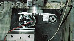
Luckily, I realised that if I mounted the base plate horizontally then the motor would be lower than the wheel surface, which would prevent the grinding of long work pieces. A solution would be to angle the base plate down at the wheel end by 3.5 deg. So I milled an angled surface on the quill clamp. The clamp is substantial enough so that the holes and milled surface have next to no effect on strength nor stiffness. It would have been easy to have overlooked this problem and it was pure luck that made me check.
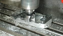
On the left, milling the clamp for the 3.5 deg angle. On the right we can be seen how the grinder base tilts downward at the wheel end.
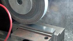
A couple of hours later and I did my first test grind and was very pleased with the finish, I did it dry but will try mist in future. I used a cheap bench grinder wheel, because it is the only one that I have with a 1.25" hole in it to fit my mandrels. I can fit wheels between 5.5" and 6.5", larger will foul the clamp and less leaves the motor lower, which only matters for long work pieces. I have a CBN 6" wheel that I got for cam grinding, that is narrower and would need more passes but it will be interesting to see the finish.
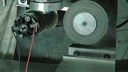
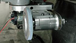
A couple views of the grinder before it had a wheel cover and after doing the first test grind on a piece of hardened steel. I was very pleased with the results.
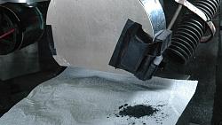
After I made a Q&D wheel cover I started to think about a dust funnel to connect to a shopvac, but in the preceding day or two I had been discussing magnets with a couple of friends and that lead me to think about using one or more magnets to collect most of the swarf. Afterall if you are grinding properly with the correct wheel then almost all of the dust is steel although many people think that it is abrasive grit. Imagine how fast the wheel would wear if that were the case. So I firstly did a quick test, I hand held a magnet to the outside of the cover and did a test grind. As can be seen in the first pic below, when I removed the magnet the collected swarf fell down. The second pic shows the swarf that I wiped off magnets, which I had taped to the cover, after I had ground the top of the hardened jaws of my mill vice. Almost 100% of the swarf was captured. It was interesting to watch from work surface height. Without the magnets the sparks would be shot off horizontally at a tangent to the contact point, also some sparks would be carried around with the wheel and exit at the rear end. With the magnets in place the spark trajectory would curl around and head for the magnets, no more exited from the rear, I had a catch system to try and collect any dust that got missed and I collected nothing.
So now I need to make a proper system for mounting the magnets. I am thinking that I should make it an eletromagnet, then when I want to clean the swarf out I'll just have to switch it off and catch the falling dust.
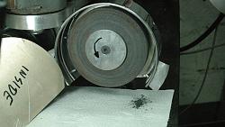
Now I have to write a simple programme to output G-code to move the table longitudinally by the required amount and then step over for the next pass. A simple bit of software that would take the need for thinking out of the equation. I also need to look for a magnetic chuck but that is not so easy to find used here in Spain, shipping would kill it from Germany or UK. I really don't want to have to make one because that WOULD take more than a couple of hours. If I have to make one then it will be an electromagnetic chuck made from surplus transformers.
I have made videos of most of the process and will post a link as soon as I get around to editing it.


 LinkBack URL
 About LinkBacks


 Reply With Quote




Bookmarks